Modular Field Cage Installation Sequence Overview
This installation sequence outlines the step-by-step process for installing the lower FC panels, completing the TPC installation, and mounting the modular field cage components. It includes the placement of beams with standoffs, translation of GP planes, mounting of profiles/racetrack modules, and making electrical connections. The use of captive nuts, fasteners, and plank blocking for support and safety considerations are also addressed.

Download Presentation

Please find below an Image/Link to download the presentation.
The content on the website is provided AS IS for your information and personal use only. It may not be sold, licensed, or shared on other websites without obtaining consent from the author.If you encounter any issues during the download, it is possible that the publisher has removed the file from their server.
You are allowed to download the files provided on this website for personal or commercial use, subject to the condition that they are used lawfully. All files are the property of their respective owners.
The content on the website is provided AS IS for your information and personal use only. It may not be sold, licensed, or shared on other websites without obtaining consent from the author.
E N D
Presentation Transcript
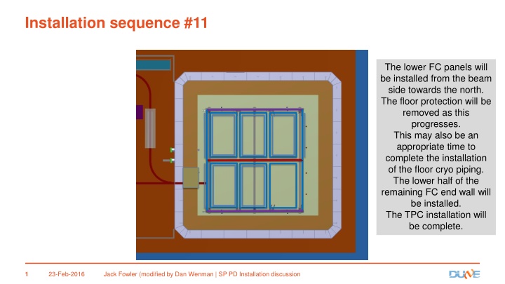
Installation sequence #11 The lower FC panels will be installed from the beam side towards the north. The floor protection will be removed as this progresses. This may also be an appropriate time to complete the installation of the floor cryo piping. The lower half of the remaining FC end wall will be installed. The TPC installation will be complete. 23-Feb-2016 Jack Fowler (modified by Dan Wenman | SP PD Installation discussion 1
FC Modular preliminary concept for manual installation Requires some kind of captive nut on the top side of the GP GP standoffs preassembled to the beam Module connection shown with a standoff that fits between profiles. 2- 4 per module/per beam? Modular FC profile assembly 2 March-2016 2 Dan Wenman FC Installation
Modular top field cage installation Beams with standoffs are installed GP is threaded through beams and secured with fasteners from the inside Modular FC assemblies are mounted to the bottom of the beams Electrical connections are made 2 March-2016 3 Dan Wenman FC Installation
Modular top field cage installation (cont.) Captive nuts on the ground plane would allow securing with fasteners from the FC side GP 2 March 2016 4 Dan Wenman FC Installation
Bottom Modular FC installation 1. Support beam with standoffs are installed 2. Working from APA to CPA the first GP planes are translated into position and mounted. (Rotated parallel to the floor into position for the last FC.) 3. The first profile/racetrack module is positioned and mounted. 4. Electrical connections are made 5. Steps are repeated until complete. 2 March 2016 5 Dan Wenman FC Installation
Comments It may be nice for electrical connections to be biased to one side for last minute access Access for installing the last modular panels will be a challenge Make it a requirement for the CPA and FC to be safe to support a person on a plank near the CPA? Blocking underneath, in line with the standoffs, to provide support for the FC beams? Need to look at real situation with piping and corrugations. Plank blocking blocking 2 March-2016 6 Dan Wenman FC Installation
winch Possible option for installing FC pulley Low profile light duty crane with 2 lift points. Crane runs on installation beams. Crane is could be designed to be fully or partially disassembled with access from the downstream side of the TPC.
Options for lifting the FC panels For ProtoDUNE and probably DUNE the lifting equipment will have to be removed before the TCO is closed. The last FC s would then be assembled in place. For protoDUNE probably makes sense to assemble all the FC in place. SLC Lifting Height: 24 ft (7.32 m) Width - stowed: 2 ft .75 in (0.63 m) Load Capacity: 650 lbs (295 kg) -24 AWP Working Height*: 42 ft 5 in (13.10 m) Lift Capacity : 350 lbs (159 kg) Platform Height: 36 ft 5 in (11.10 m) -36S Genie superlift Other vendors: Vermette Machining, Sumner 2 March 2016 8 Dan Wenman FC Installation
Back up slides 23-Feb-2016 9 Jack Fowler | SP PD Installation discussion
Installation sequence #4 The beam side end wall FC will be installed. 23-Feb-2016 Jack Fowler | SP PD Installation discussion 10
Installation sequence #5 The 3 upper field cage panels will be installed. Note: Access to the CE on APAs 1, 2 and 3 is now not possible. 23-Feb-2016 Jack Fowler | SP PD Installation discussion 11
Completion of the Jura FC as follows: Install the upper half of the north FC wall. Disassemble scaffolding in this drift area. Install the lower FC panels from beam side to N side. Removal of floor protective panels will be completed and the areas are covered with the FC panels. Install the lower half of the north FC wall from the outside of drift volume. Installation sequence #6 HV can be installed at this point. Need to evaluate the optimal time for this. 23-Feb-2016 Jack Fowler | SP PD Installation discussion 12
Installation sequence #9 The upper half of the north Seleve end wall FC will be installed. The upper two FC panels may be installed at this point. This will block access to the CE for two of the APAs. After this is complete, all of the remaining FC panels must be moved and stored inside the cryostat for the closing of the TCO. Also all of the materials for closing the TCO must be in the cryostat prior before beginning the closure. Is there enough storage and work space available? 23-Feb-2016 Jack Fowler | SP PD Installation discussion 13
Installation sequence #10 After the TCO is closed, the beam side Seleve FC will be installed. Then the final upper FC will be installed. The scaffolding from the Seleve side drift can be removed. After the TCO is closed, access to the cryostat will only be possible through the manholes. All materials not in the cryostat must fit through the manhole. All tooling inside the cryostat can only be removed through the manhole. 23-Feb-2016 Jack Fowler | SP PD Installation discussion 14


")