E80 Rocket Engineering Project Overview


E
n
g
i
n
e
e
r
i
n
g
8
0
–
S
p
r
i
n
g
2
0
1
5
F
l
i
g
h
t
H
a
r
d
w
a
r
e
1
Three Words You Should Know!
MAKE IT HAPPEN
ENGINEERING 80
2
Flight Hardware
MAKING IT HAPPEN
ENGINEERING 80
Flight Hardware
3
Three Words You Should Know!
“MAKE IT HAPPEN”?
ENGINEERING 80
4
How does one
Flight Hardware
What’s Your Problem Statement?
ENGINEERING 80
5
SOURCE: http://www.clker.com/cliparts/6/5/b/f/11949864691020941855smiley114.svg.med.png
Flight Hardware
A “ONE-PAGER”…
•
Problem Statement (or Purpose, or Goal)
•
The final E80 project needs to be completed to pass the course
•
Success Criteria (envision successfully crossing the finish line)
•
Design, build, and test a rocket that meets E80 requirements, and
submit a final report and give a final presentation
•
Strategies (how are you going to get to that finish line?)
•
Work as a team to meet all weekly project deliverables
•
Timeline (detailed plan for implementing the strategies)
ENGR 106 Lecture 3
6
Flight Hardware
Sample
Timeline for
Section 2
Today We Will Discuss…
•
E80 Rocket Requirements
•
Surviving Launch and Recovery
•
Rocket Construction
•
Deliverables
ENGINEERING 80
Flight Hardware
7
E80 Engineering Rocket Requirements
•
Payload Dimensions
•
Sensor Requirements
•
Speed of Response
•
Power Requirements
•
Acceleration, Shock, and Vibration
•
Temperature Profile
•
Construction Standards
ENGINEERING 80
8
Flight Hardware
Payload Dimensions
•
You will be assigned either an…
•
Aerotech Arreaux <
.rkt
> <
.ork
> <
.zip
>
•
Payload Section ID: 1.80 inches
•
Payload Section Length:
12.00 inches
•
Aerotech Barracuda <
.rkt
> <
.ork
> <
.zip
>
•
Payload Section ID: 1.80 inches
•
Payload Section Length:
22.75 inches
ENGINEERING 80
9
ID = 1.80”
Length = 12” -or- 22.75”
If you feel you need
a rocket different
from the assigned,
write a proposal
explaining the
technical reasons
and give it to your
section Prof.
Flight Hardware
Teams
1, 3, & 5
Teams
2 & 4
Your Precious Payload – The PC Board
•
Top laid out like your protoboard
•
4 exterior buses slightly closer
•
1 extra power bus
•
Bottom has connectors for a data logger
•
4 Holes for mounting
•
2 holes for mounting battery holder
ENGINEERING 80
Flight Hardware
10
If it works on your
protoboard, then it will
work on the PC Board
Chip for Chip
Wire for Wire
Payload Sections
•
PC board matches Aerotech body tubing diameter
•
Arreaux payload section too short
•
Barracuda payload section too long
•
An Aerotech body tube that fits the PC board will be provided
ENGINEERING 80
Flight Hardware
11
ID = 1.80”
Length = 10.10”
Data Logging
•
How do you acquire and log data in the rocket?
ENGINEERING 80
Flight Hardware
12
ID = 1.80”
Length = 10.10”
Your Precious Payload – The PC Board
•
Center has place for 5 V regulator + three more
•
Regulators can tie common to ground or not
•
Bottom has connectors for data logger
ENGINEERING 80
Flight Hardware
13
Your Precious Payload – The Data Logger
•
Created and programmed by Tyler Smelt
•
16 channels (Can measure up to 16 sensors)
•
16-bit resolution
•
Max 400 kSPS composite rate (25 kSPS/chan)
•
Max 200 kSPS on single channel (read in pairs)
•
Power with 6 V to 20 V (9 V recommended)
•
Uses microSD for storage (have 16 GB cards)
•
Need to tape/secure the SD card in the reader!
•
Input range 0 to 3.3 V
•
Input Impedance ≈2.2kΩ (MyDAQ is 10 GΩ)
•
Low impedance, may need to buffer your input signals
•
Set parameters with Config File (Initialize on PC)
•
Have VI and .m file to read binary data files
•
PIC-32 microcontroller; Two AD7689 A/D Chips
ENGINEERING 80
Flight Hardware
14
MORE INFO ON THE
E80 WEBSITE!
Single–Sided Circuits
•
Data logger expects 0 V to 3.3 V signals
•
Classical op-amp circuit power ±15 V
•
Low-voltage op-amp circuit power
•
±1.4 V to ±3 V
•
0-to-2.8 V to 0-to-6 V
•
Signal offset
•
Normal signal that goes above and below
zero will need DC offset
•
Reference offset
•
Virtual ground
•
This is where we want all signals referenced
•
WHAT IS A VIRTUAL GROUND?
ENGINEERING 80
Flight Hardware
15
Inverting Amps
ENGINEERING 80
Flight Hardware
16
LOW POWER OP-AMP
Inverting Amps
ENGINEERING 80
Flight Hardware
17
What are these for?
LOW POWER OP-AMP
Inverting Amps
ENGINEERING 80
Flight Hardware
18
These filter out noise in the
power lines; Use them!
LOW POWER OP-AMP
Inverting Amps
ENGINEERING 80
Flight Hardware
19
LOW POWER OP-AMP
Inverting Amps
ENGINEERING 80
Flight Hardware
20
Virtual Ground
This offsets the op-amp so
that the signal is centered
between 0 and 5 V
Low side of battery
High side of battery
LOW POWER OP-AMP
Inverting Amps
ENGINEERING 80
Flight Hardware
21
Virtual Ground
This offsets the op-amp so
that the signal is centered
between 0 and 5 V
Low side of battery
High side of battery
If you are powering your circuit by battery and you have a single
sided supply, you need to think of creating a virtual ground halfway
between your low and high on your op amp; then offset your signal
so that you have your average value in the middle instead of zero
Data logger needs 0 to 3.3 V;
You could go from 0 to 3.3 V with 1.8 V as center
LOW POWER OP-AMP
Non-Inverting Amps
ENGINEERING 80
Flight Hardware
22
Scientific vs. Engineering Measurements
ENGINEERING 80
Flight Hardware
23
WHAT’S THE
DIFFERENCE?
Scientific vs. Engineering Measurements
ENGINEERING 80
Flight Hardware
24
Engineering
Measurements
“What you
measure about
a rocket.”
Scientific
Measurements
“What you
measure with a
rocket.”
Sensor Requirement
•
You are required to have a
MINIMUM of 2
types of sensors
•
One thermocouple and one thermistor would count
•
Two thermocouples would
NOT
count
ENGINEERING 80
Flight Hardware
25
What Does a PC Board with Sensors Look Like?
ENGINEERING 80
Flight Hardware
26
WHERE WOULD I
FIND THIS?
What Does a PC Board with Sensors Look Like?
ENGINEERING 80
Flight Hardware
27
SOURCE: http://www.eng.hmc.edu/NewE80/LargePhotos/KC20120421_IMG_1658.jpg
Sensor Requirement
•
You are required to have a
MINIMUM of 2
types of sensors
•
One thermocouple and one thermistor would count
•
Two thermocouples would
NOT
count
ENGINEERING 80
Flight Hardware
28
SOURCE: http://www.eng.hmc.edu/NewE80/LargePhotos/KC20120421_IMG_1658.jpg
Speed of Sensor Response
•
We recommend using…
•
At least one sensor with a time constant faster than 1 ms
•
Bandwidth ≥ 1 kHz
•
Sensor adequate:
•
The bandwidth of the sensor is 10 times higher than the
phenomenon that you want to measure
•
Sensor Needs deconvolution:
•
Sensor is “Hopeless”:
ENGINEERING 80
Flight Hardware
29
Effect of Temperature Sensor Time Constant
ENGINEERING 80
Flight Hardware
30
Temperature Measurement Devices in Lab
ENGINEERING 80
Flight Hardware
31
>
Effect of Temperature Sensor Time Constant
ENGINEERING 80
Flight Hardware
32
PML Phobos on H123W-M
Effect of Temp. Sensor Time Constant
At standard lapse rate
∆T = –7.8°C @ 1200 m AGL
•
Temperature drops by 0.0065
o
C
for every meter going up
Effect of Temperature Sensor Time Constant
ENGINEERING 80
Flight Hardware
33
PML Phobos on H123W-M
Effect of Temp. Sensor Time Constant
PML Phobos on H123W-M
Hysteresis of Temp. sensor
Actual Data from Sensors
ENGINEERING 80
Flight Hardware
34
Actual Data from Sensors
ENGINEERING 80
Flight Hardware
35
Speed of Sound = 343 m/s
Actual Data from Sensors
ENGINEERING 80
Flight Hardware
36
Actual Data from Sensors
ENGINEERING 80
Flight Hardware
37
WHY THE DISCREPANCY?
Actual Data from Sensors
ENGINEERING 80
Flight Hardware
38
Pnut assumes Standard Atmospheric Model
•
Dry Air
•
Temperature Varies Linearly
Sensor Requirement
•
You are required to have a
MINIMUM
of 2 types of sensors
•
One thermocouple and one thermistor would count
•
Two thermocouples would
NOT
count
•
WHAT OTHER TYPES OF SENSORS COULD WE USE?
•
Pressure Altimeter
•
Pitot-Static Tube
•
Gas/Humidity Sensor
•
Vibration Sensor; Light Sensor
ENGINEERING 80
Flight Hardware
39
Sensor Requirement
•
You are required to have a
MINIMUM
of 2 types of sensors
•
One thermocouple and one thermistor would count
•
Two thermocouples would
NOT
count
•
WHAT OTHER TYPES OF SENSORS COULD WE USE?
•
Pressure Altimeter
•
Pitot-Static Tube
•
Accelerometer/Rate Gyroscope
•
Gas/Humidity Sensor; Vibration Sensor; Light Sensor
ENGINEERING 80
Flight Hardware
40
Sensor Requirements
•
Air Temperature Sensor
•
Sensor in the free stream
•
Pressure Altimeter
•
No flow; 3 or 4 symmetric pressure taps
•
Accelerometer/Rate Gyroscope
•
Known fixed orientation
•
Means to deal with baseline and drift
•
Pitot-Static Tube
•
Pitot tube in free stream and direction of motion
•
Static Tap should be normal to the flow
•
Preferable 4+ “calibers” (rocket tube diameters) from
the nose cone
•
Multiple in symmetric pattern is best
ENGINEERING 80
Flight Hardware
41
SOURCE: http://www.ipscustom.com/ProdImages/Wire_E_tt_pp_m.gif
SOURCE: http://web.stanford.edu/class/me220/data/lectures/lect05/static_probe.gif
SOURCE: http://cdn2.bigcommerce.com/server2900/730e2/products/56/images/248/PnutTop__64333.1405342120.1280.640.png?c=2
Your Team has a Budget
of $50
Sensor Requirements
•
Light Sensor
•
Proper orientation and view field
•
Vibration Sensor
•
Best on anti-node; avoid node
•
Nor for DC strain
•
Gas Humidity Sensor
•
Gas flow to sensor is desired
•
Particle/Dust Sensor
•
Gas flow through sensor
•
If optical, reduce or eliminate background light
•
Often needs pulse train
ENGINEERING 80
Flight Hardware
42
SOURCE: http://www.digikey.com/product-detail/en/HIH-5030-
001/480-3294-1-ND/2061078
SOURCE: http://www.digikey.com/product-search/en?vendor=0&keywords=605-00004-ND
SOURCE: http://www.digikey.com/product-
detail/en/GP2Y1010AU0F/425-2068-ND/720164
Sensor Placement
•
Sensors need to be placed in locations where a measurement is desired
•
Easiest in Payload Section
•
Next easiest in Nosecone
•
Ports/Channels to rout to exterior
•
Don’t forget separation for recovery
•
Can run (very long) wires through shock cord
•
Can make connector that separates at recovery
•
Can have separate sections
ENGINEERING 80
Flight Hardware
43
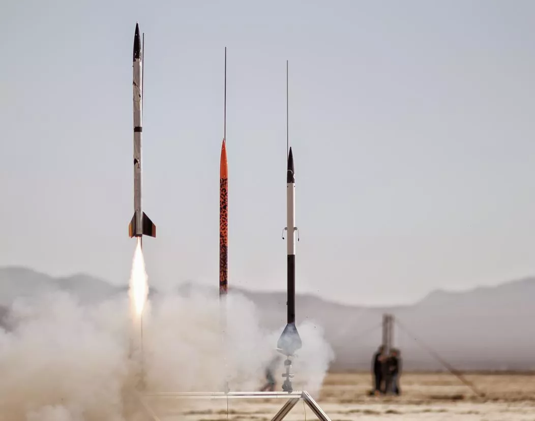
What Does a Rocket with Sensors Look Like?
ENGINEERING 80
Flight Hardware
44
WHERE WOULD I
FIND THIS?
What Does a Rocket with Sensors Look Like?
ENGINEERING 80
Flight Hardware
45
SOURCE: http://www.eng.hmc.edu/NewE80/LargePhotos/20140419_E80-FirstLaunch_SMM_341.jpg
Video Camera
•
Battery charged by USB
•
40 minute battery time on full
charge
•
Creates 720P .mov file on microSD
•
10 minutes per 1 GB
•
On 16 GB card will run out of battery
before storage
•
Physical Mounting
•
Method
•
Duct tape? Electrical tape?
•
Location
•
Center of pressure?
•
Field of View
ENGINEERING 80
Flight Hardware
46
Power Requirements
•
Power Inputs
•
Data Logger: 6 V to 20 V
•
IMU: 5 V (regulated) & 3 V to 3.3 V (regulated)
•
AD623AN: 3 V to 12 V or ±1.5 V to ±6 V
•
MPC 60XX: 2.7 V to 6 V
•
Other sensors – TBD
•
Must measure current draw of final circuit
•
Batteries must power for 1 hour minimum
Battery capacity (in mAh) / Average current consumption (in mA) = Hours of expected runtime
•
Turn on before launch, stay on during flight, turn off after recovery.
ENGINEERING 80
Flight Hardware
47
Power Sources
•
Power sources
•
9 V lithium, 750 mAh
•
1.5 V
•
AAA Alkaline, 1000 mAh; Lithium, 1200 mAh
•
AA Alkaline, 2700 mAh; Lithium, 3000 mAh
•
12 V (NEDEA- 1811A), 55 mAh
•
LiPo (Rechargable, High Power Density, Special Charger, HazMat)
•
3.7 V, up to 5000 mAh
•
7.4 V, up to 5000 mAh
•
11.1 V, up to 5000 mAh
•
NiMH (Rechargable)
•
NiCd (Rechargable)
•
Your team will decide on which power source to use
ENGINEERING 80
Flight Hardware
48
Your Team has a Budget of
$50
Surviving
•
What does your rocket have to
survive during launch?
ENGINEERING 80
Flight Hardware
49
BE THE ROCKET
Temperature
1) Temperature at Launch
•
Often –2°C at 6 AM
•
Solar heating of payload section to 50°C+
•
At standard lapse rate ∆T = –7.8°C @ 1200 m AGL
•
Temperature drops by 0.0065
o
C for every meter going up
ENGINEERING 80
Flight Hardware
50
Standards for Parts
Commercial Grade: 0°C to 70°C
Industrial Grade: –40°C to 85°C
Military Grade: –55°C to 125°C
Acceleration
2) Acceleration
•
From motor, 6g to (50+)g
•
Use RockSim or OpenRocket to estimate
ENGINEERING 80
Flight Hardware
51
Vibration
ENGINEERING 80
Flight Hardware
52
3) Vibration (
What causes vibration?
)
BE THE ROCKET
Vibration
ENGINEERING 80
Flight Hardware
53
3) Vibration (
What causes vibration?
)
•
From motor
•
From aerodynamics
•
From shock impulse
Amplified at resonant frequencies
Use viscoelastic damping materials
SOURCE: http://www.sorbothane.com/blog/wp-content/uploads/2010/07/engine-vibrations.jpg
Shock
ENGINEERING 80
Flight Hardware
54
4) Shock (
What causes shock?
)
BE THE ROCKET
Shock
ENGINEERING 80
Flight Hardware
55
4) Shock (
What causes shock?
)
•
Deployment charge, 2 g to 20+ g
•
From parachute, 1 g to 50+ g
•
From ballistic landing, 200+ g
Surviving
ENGINEERING 80
Flight Hardware
56
•
What does your rocket have to
survive during launch?
1.
Temperature
2.
Acceleration
3.
Vibration
4.
Shock
Constructing Your Rocket
•
NAR or TRA safety Code is mandatory.
•
Materials:
I will use only lightweight materials such as paper, wood,
rubber, plastic, fiberglass, or when necessary ductile metal, for the
construction of my rocket.
•
Motors:
I will use only certified, commercially made rocket motors,
and will not tamper with these motors or use them for any purposes
except those recommended by the manufacturer. I will not allow
smoking, open flames, nor heat sources within 25 feet of these
motors.
ENGINEERING 80
Flight Hardware
57
Constructing Your Rocket
•
Adhesives must be used under fume hood, in spray-paint booth, or
outdoors.
•
Neoprene gloves required. Eye protection required
•
G10 Fiberglass (PML fins) must be wet sanded or with full respiratory
protection. Neoprene gloves strongly recommended.
•
No sharp implements permitted when removing plastic rivets.
•
Spray painting only permitted in paint booth or outdoors (not by Libra
Complex). Skin & eye protection required.
•
If you follow the
unmodified
instructions for the rockets, you will
NOT
be able to fly them.
•
Aerotech requires motor retainer, longer motor mount, modified placement,
and removal of motor hook, thrust ring, and thrust ring flange
ENGINEERING 80
Flight Hardware
58
Rocket Construction
•
Motor retainers attached with JB Weld ONLY!
•
Cyanoacrylic/Super-Glue (Aerotech)
•
Make SURE you have adequate ventilation
•
ALWAYS use skin protection (neoprene gloves)
•
Usually sets in 30 s to 20 min
•
Can use accelerator (we have limited supplies)
•
Accelerator on one surface + Super-Glue on other surface = instant bond
when joined.
•
Will have to dribble on some internal joints
•
Epoxy clay
•
Not quite as strong as epoxy
•
Very useful for fillets and custom mounts
•
You always need less than you think
ENGINEERING 80
Flight Hardware
59
Rocket Hints
•
For Aerotech kits…
•
There is no need for the 24 mm motor adaptor.
•
Make sure the fins snap easily into the Fink Locks BEFORE putting the Motor
Tube Assembly into the Body Tube.
•
It’s very difficult to reconnect the shock cord to the nose cone. An extension
from the screw eye to the end of the coupler makes the process much easier.
ENGINEERING 80
Flight Hardware
60
Deliverables
•
Week 1
•
Scientific and/or Engineering objectives
•
Select sensors (min: 2, MAX: 16)
•
Parts list (especially to order)
•
Complete schematic
•
Show all calculations; bypass capacitors; power
•
Check off by Section Prof & Prof Spjut
•
Week 2
•
Complete protoboard
•
Measured current draw
•
Demonstrate functionality
•
Check off by Section Prof & Prof Spjut
ENGINEERING 80
Flight Hardware
61
NO RESTRICTIONS ON
WHEN YOU DO YOUR
WORK.
•
However, priority for
resources goes to groups
that were assigned to
that lab section.
•
Need to show up to your
lab section for the
check-off.
Deliverables
•
Week 3
•
Fully populated PC board
•
Demonstrate functionality
•
Data acquisition works and is demonstrated
•
Check off by Section Prof & Prof Spjut
•
Week 4
•
Completed Rocket
•
Complete ground and analysis procedures
•
Completed launch checklist (you have to
DO steps)
•
Loaded launch motors
ENGINEERING 80
Flight Hardware
62
NO RESTRICTIONS ON
WHEN YOU DO YOUR
WORK.
•
However, priority for
resources goes to groups
that were assigned to
that lab section.
•
Need to show up to your
lab section for the
check-off.
Deliverables
•
Week 5
•
List lessons learned
•
Fix & correct things
•
Load launch motors
•
Week 6
•
Analyze data
•
Write Final Report
•
Prepare Final Presentation
ENGINEERING 80
Flight Hardware
63
NO RESTRICTIONS ON
WHEN YOU DO YOUR
WORK.
•
However, priority for
resources goes to groups
that were assigned to
that lab section.
•
Need to show up to your
lab section for the
check-off.
A “ONE-PAGER”…
•
Problem Statement (or Purpose, or Goal)
•
The final E80 project needs to be completed to pass the course
•
Success Criteria (envision successfully crossing the finish line)
•
Design, build, and test a rocket that meets E80 requirements, and
submit a final report and give a final presentation
•
Strategies (how are you going to get to that finish line?)
•
Work as a team to meet all weekly project deliverables
•
Timeline (detailed plan for implementing the strategies)
ENGR 106 Lecture 3
64
Flight Hardware
Sample
Timeline for
Section 2
Good Luck Over the Next 7 Weeks!
MAKE IT HAPPEN!
ENGINEERING 80
65
Flight Hardware
Dive into the details of the E80 rocket engineering project for the Spring 2015 semester. Explore the key components such as flight hardware, problem statements, project timeline, and rocket requirements. Get insights into the strategies, success criteria, and deliverables associated with this challenging course. Stay tuned to learn about surviving launch and recovery, rocket construction, and more exciting aspects of the project.

Download Presentation

Please find below an Image/Link to download the presentation.
The content on the website is provided AS IS for your information and personal use only. It may not be sold, licensed, or shared on other websites without obtaining consent from the author. Download presentation by click this link. If you encounter any issues during the download, it is possible that the publisher has removed the file from their server.
E N D
Presentation Transcript
Engineering 80 Spring 2015 Flight Hardware Flight Hardware 1
Three Words You Should Know! MAKE IT HAPPEN ENGINEERING 80 Flight Hardware 2
MAKING IT HAPPEN ENGINEERING 80 Flight Hardware 3
Three Words You Should Know! How does one MAKE IT HAPPEN ? ENGINEERING 80 Flight Hardware 4
Whats Your Problem Statement? SOURCE: http://www.clker.com/cliparts/6/5/b/f/11949864691020941855smiley114.svg.med.png ENGINEERING 80 Flight Hardware 5
A ONE-PAGER Problem Statement (or Purpose, or Goal) The final E80 project needs to be completed to pass the course Success Criteria (envision successfully crossing the finish line) Design, build, and test a rocket that meets E80 requirements, and submit a final report and give a final presentation Strategies (how are you going to get to that finish line?) Work as a team to meet all weekly project deliverables Timeline (detailed plan for implementing the strategies) TASK Meet Week 1 Deliverables Meet Week 2 Deliverables Meet Week 3 Deliverables Meet Week 4 Deliverables Meet Week 5 Deliverables Meet Week 6 Deliverables Give Final Presentation Start End Status In Progress Not Started Not Started Not Started Not Started Not Started Not Started 3/12/2015 3/25/2015 4/1/2015 4/8/2015 4/15/2015 4/22/2015 5/4/2015 3/25/2015 4/1/2015 4/8/2015 4/15/2015 4/22/2015 5/4/2015 5/4/2015 Sample Timeline for Section 2 ENGR 106 Lecture 3 Flight Hardware 6
Today We Will Discuss E80 Rocket Requirements Surviving Launch and Recovery Rocket Construction Deliverables ENGINEERING 80 Flight Hardware 7
E80 Engineering Rocket Requirements Payload Dimensions Sensor Requirements Speed of Response Power Requirements Acceleration, Shock, and Vibration Temperature Profile Construction Standards ENGINEERING 80 Flight Hardware 8
Payload Dimensions Length = 12 -or- 22.75 ID = 1.80 You will be assigned either an Aerotech Arreaux <.rkt> <.ork> <.zip> Payload Section ID: 1.80 inches Payload Section Length: 12.00 inches Aerotech Barracuda <.rkt> <.ork> <.zip> Payload Section ID: 1.80 inches Payload Section Length: 22.75 inches If you feel you need a rocket different from the assigned, write a proposal explaining the technical reasons and give it to your section Prof. Teams 1, 3, & 5 Teams 2 & 4 ENGINEERING 80 Flight Hardware 9
Your Precious Payload The PC Board Top laid out like your protoboard 4 exterior buses slightly closer 1 extra power bus Bottom has connectors for a data logger 4 Holes for mounting 2 holes for mounting battery holder If it works on your protoboard, then it will work on the PC Board Chip for Chip Wire for Wire ENGINEERING 80 Flight Hardware 10
Payload Sections PC board matches Aerotech body tubing diameter Arreaux payload section too short Barracuda payload section too long An Aerotech body tube that fits the PC board will be provided Length = 10.10 ID = 1.80 ENGINEERING 80 Flight Hardware 11
Data Logging How do you acquire and log data in the rocket? Length = 10.10 ID = 1.80 ENGINEERING 80 Flight Hardware 12
Your Precious Payload The PC Board Center has place for 5 V regulator + three more Regulators can tie common to ground or not Bottom has connectors for data logger ENGINEERING 80 Flight Hardware 13
Your Precious Payload The Data Logger Created and programmed by Tyler Smelt 16 channels (Can measure up to 16 sensors) 16-bit resolution Max 400 kSPS composite rate (25 kSPS/chan) Max 200 kSPS on single channel (read in pairs) Power with 6 V to 20 V (9 V recommended) Uses microSD for storage (have 16 GB cards) Need to tape/secure the SD card in the reader! Input range 0 to 3.3 V Input Impedance 2.2k (MyDAQ is 10 G ) Low impedance, may need to buffer your input signals Set parameters with Config File (Initialize on PC) Have VI and .m file to read binary data files PIC-32 microcontroller; Two AD7689 A/D Chips MORE INFO ON THE E80 WEBSITE! ENGINEERING 80 Flight Hardware 14
SingleSided Circuits Data logger expects 0 V to 3.3 V signals Classical op-amp circuit power 15 V Low-voltage op-amp circuit power 1.4 V to 3 V 0-to-2.8 V to 0-to-6 V Signal offset Normal signal that goes above and below zero will need DC offset Reference offset Virtual ground This is where we want all signals referenced WHAT IS A VIRTUAL GROUND? ENGINEERING 80 Flight Hardware 15
Inverting Amps LOW POWER OP-AMP ENGINEERING 80 Flight Hardware 16
Inverting Amps LOW POWER OP-AMP What are these for? ENGINEERING 80 Flight Hardware 17
Inverting Amps LOW POWER OP-AMP These filter out noise in the power lines; Use them! ENGINEERING 80 Flight Hardware 18
Inverting Amps LOW POWER OP-AMP ENGINEERING 80 Flight Hardware 19
Inverting Amps LOW POWER OP-AMP Virtual Ground This offsets the op-amp so that the signal is centered between 0 and 5 V High side of battery Low side of battery ENGINEERING 80 Flight Hardware 20
Inverting Amps LOW POWER OP-AMP If you are powering your circuit by battery and you have a single sided supply, you need to think of creating a virtual ground halfway between your low and high on your op amp; then offset your signal so that you have your average value in the middle instead of zero Data logger needs 0 to 3.3 V; You could go from 0 to 3.3 V with 1.8 V as center Virtual Ground This offsets the op-amp so that the signal is centered between 0 and 5 V High side of battery Low side of battery ENGINEERING 80 Flight Hardware 21
Non-Inverting Amps ENGINEERING 80 Flight Hardware 22
Scientific vs. Engineering Measurements WHAT S THE DIFFERENCE? ENGINEERING 80 Flight Hardware 23
Scientific vs. Engineering Measurements Engineering Measurements What you measure about a rocket. Scientific Measurements What you measure with a rocket. ENGINEERING 80 Flight Hardware 24
Sensor Requirement You are required to have a MINIMUM of 2 types of sensors One thermocouple and one thermistor would count Two thermocouples would NOT count ENGINEERING 80 Flight Hardware 25
What Does a PC Board with Sensors Look Like? WHERE WOULD I FIND THIS? ENGINEERING 80 Flight Hardware 26
What Does a PC Board with Sensors Look Like? SOURCE: http://www.eng.hmc.edu/NewE80/LargePhotos/KC20120421_IMG_1658.jpg ENGINEERING 80 Flight Hardware 27
Sensor Requirement You are required to have a MINIMUM of 2 types of sensors One thermocouple and one thermistor would count Two thermocouples would NOT count SOURCE: http://www.eng.hmc.edu/NewE80/LargePhotos/KC20120421_IMG_1658.jpg ENGINEERING 80 Flight Hardware 28
Speed of Sensor Response We recommend using At least one sensor with a time constant faster than 1 ms Bandwidth 1 kHz tS< 0.1tP Sensor adequate: The bandwidth of the sensor is 10 times higher than the phenomenon that you want to measure Sensor Needs deconvolution: 0.1tP<tS<10tP tS>10tP Sensor is Hopeless : ENGINEERING 80 Flight Hardware 29
Effect of Temperature Sensor Time Constant ENGINEERING 80 Flight Hardware 30
Temperature Measurement Devices in Lab > ENGINEERING 80 Flight Hardware 31
Effect of Temperature Sensor Time Constant PML Phobos on H123W-M Effect of Temp. Sensor Time Constant At standard lapse rate T = 7.8 C @ 1200 m AGL Temperature drops by 0.0065oC for every meter going up ENGINEERING 80 Flight Hardware 32
Effect of Temperature Sensor Time Constant PML Phobos on H123W-M Effect of Temp. Sensor Time Constant PML Phobos on H123W-M Hysteresis of Temp. sensor ENGINEERING 80 Flight Hardware 33
Actual Data from Sensors ENGINEERING 80 Flight Hardware 34
Actual Data from Sensors Speed of Sound = 343 m/s ENGINEERING 80 Flight Hardware 35
Actual Data from Sensors ENGINEERING 80 Flight Hardware 36
Actual Data from Sensors WHY THE DISCREPANCY? ENGINEERING 80 Flight Hardware 37
Actual Data from Sensors Pnut assumes Standard Atmospheric Model Dry Air Temperature Varies Linearly ENGINEERING 80 Flight Hardware 38
Sensor Requirement You are required to have a MINIMUM of 2 types of sensors One thermocouple and one thermistor would count Two thermocouples would NOT count WHAT OTHER TYPES OF SENSORS COULD WE USE? Pressure Altimeter Pitot-Static Tube Gas/Humidity Sensor Vibration Sensor; Light Sensor ENGINEERING 80 Flight Hardware 39
Sensor Requirement You are required to have a MINIMUM of 2 types of sensors One thermocouple and one thermistor would count Two thermocouples would NOT count WHAT OTHER TYPES OF SENSORS COULD WE USE? Pressure Altimeter Pitot-Static Tube Accelerometer/Rate Gyroscope Gas/Humidity Sensor; Vibration Sensor; Light Sensor ENGINEERING 80 Flight Hardware 40
Sensor Requirements Your Team has a Budget of $50 Air Temperature Sensor Sensor in the free stream Pressure Altimeter No flow; 3 or 4 symmetric pressure taps Accelerometer/Rate Gyroscope Known fixed orientation Means to deal with baseline and drift Pitot-Static Tube Pitot tube in free stream and direction of motion Static Tap should be normal to the flow Preferable 4+ calibers (rocket tube diameters) from the nose cone Multiple in symmetric pattern is best SOURCE: http://cdn2.bigcommerce.com/server2900/730e2/products/56/images/248/PnutTop__64333.1405342120.1280.640.png?c=2 SOURCE: http://www.ipscustom.com/ProdImages/Wire_E_tt_pp_m.gif SOURCE: http://web.stanford.edu/class/me220/data/lectures/lect05/static_probe.gif ENGINEERING 80 Flight Hardware 41
Sensor Requirements Light Sensor Proper orientation and view field Vibration Sensor Best on anti-node; avoid node Nor for DC strain Gas Humidity Sensor Gas flow to sensor is desired Particle/Dust Sensor Gas flow through sensor If optical, reduce or eliminate background light Often needs pulse train SOURCE: http://www.digikey.com/product-search/en?vendor=0&keywords=605-00004-ND SOURCE: http://www.digikey.com/product-detail/en/HIH-5030- 001/480-3294-1-ND/2061078 SOURCE: http://www.digikey.com/product- detail/en/GP2Y1010AU0F/425-2068-ND/720164 ENGINEERING 80 Flight Hardware 42
Sensor Placement Sensors need to be placed in locations where a measurement is desired Easiest in Payload Section Next easiest in Nosecone Ports/Channels to rout to exterior Don t forget separation for recovery Can run (very long) wires through shock cord Can make connector that separates at recovery Can have separate sections ENGINEERING 80 Flight Hardware 43
What Does a Rocket with Sensors Look Like? WHERE WOULD I FIND THIS? ENGINEERING 80 Flight Hardware 44
What Does a Rocket with Sensors Look Like? SOURCE: http://www.eng.hmc.edu/NewE80/LargePhotos/20140419_E80-FirstLaunch_SMM_341.jpg ENGINEERING 80 Flight Hardware 45
Video Camera Battery charged by USB 40 minute battery time on full charge Creates 720P .mov file on microSD 10 minutes per 1 GB On 16 GB card will run out of battery before storage Physical Mounting Method Duct tape? Electrical tape? Location Center of pressure? Field of View ENGINEERING 80 Flight Hardware 46
Power Requirements Power Inputs Data Logger: 6 V to 20 V IMU: 5 V (regulated) & 3 V to 3.3 V (regulated) AD623AN: 3 V to 12 V or 1.5 V to 6 V MPC 60XX: 2.7 V to 6 V Other sensors TBD Must measure current draw of final circuit Batteries must power for 1 hour minimum Battery capacity (in mAh) / Average current consumption (in mA) = Hours of expected runtime Turn on before launch, stay on during flight, turn off after recovery. ENGINEERING 80 Flight Hardware 47
Power Sources Your Team has a Budget of $50 Power sources 9 V lithium, 750 mAh 1.5 V AAA Alkaline, 1000 mAh; Lithium, 1200 mAh AA Alkaline, 2700 mAh; Lithium, 3000 mAh 12 V (NEDEA- 1811A), 55 mAh LiPo (Rechargable, High Power Density, Special Charger, HazMat) 3.7 V, up to 5000 mAh 7.4 V, up to 5000 mAh 11.1 V, up to 5000 mAh NiMH (Rechargable) NiCd (Rechargable) Your team will decide on which power source to use ENGINEERING 80 Flight Hardware 48
Surviving What does your rocket have to survive during launch? BE THE ROCKET ENGINEERING 80 Flight Hardware 49
Temperature 1) Temperature at Launch Often 2 C at 6 AM Solar heating of payload section to 50 C+ At standard lapse rate T = 7.8 C @ 1200 m AGL Temperature drops by 0.0065oC for every meter going up Standards for Parts Commercial Grade: 0 C to 70 C Industrial Grade: 40 C to 85 C Military Grade: 55 C to 125 C ENGINEERING 80 Flight Hardware 50