Understanding Contour Surveying in Land Assessment
Contour surveying involves determining the elevation of points on the ground to create contour maps, aiding in land assessment and design work. The process includes defining contour lines, establishing vertical and horizontal controls, determining contour intervals, and employing methods for surveying and interpolating contour points. Various instruments like theodolites are used for accurate measurements, and different methods such as direct and indirect approaches are utilized for effective contour surveying.

Download Presentation

Please find below an Image/Link to download the presentation.
The content on the website is provided AS IS for your information and personal use only. It may not be sold, licensed, or shared on other websites without obtaining consent from the author. Download presentation by click this link. If you encounter any issues during the download, it is possible that the publisher has removed the file from their server.
E N D
Presentation Transcript
Contour survey; introduction Gulshan Kumar School of Fisheries
Contour survey A contour or a contour line may be defined as the line of intersection of a level surface with the surface of ground. This means every point on a contour line has the same altitude as that of the assumed intersecting surface. Contouring in surveying is the determination of elevation of various points on the ground and fixing these points of same horizontal positions in the contour map.
For contouring vertical control leveling work is carried out simultaneously with horizontal control chain survey or compass survey or plane table survey. If the theodolite is used, both horizontal and vertical controls can be achieved from the same instrument. Based on the instruments used one can classify the contouring in different groups.
Contour Interval and Horizontal Equivalent: The constant vertical distance between two consecutive contours is called the contour Interval and the horizontal distance between any two adjacent contours is termed as the horizontal equivalent. The horizontal equivalent depends upon the slope of the ground. For large scale maps of flat country, for building sites for detailed design work and for calculation of quantities of earth work: 0.2 to 0.5 m contour interval is sufficient.
Methods of Contour Surveying There are two methods of contour surveying: Direct method It consists in finding vertical and horizontal controls of the points which lie on the selected contour line. For vertical control, levelling instrument is commonly used. Indirect method
In this method, levels are taken at some selected points and their levels are reduced. Thus in this method horizontal control is established first and then the levels of those points found. After locating the points on the plan, reduced levels are marked and contour lines are interpolated between the selected points. For selecting points anyone of the following methods may be used: (a) Method of squares, (b) Method of cross-section, or (c) Radial line method.
For interpolating contour points between the two points any one of the following method may be used: (a) Estimation (b) Arithmetic calculation (c) Mechanical or graphical method. The methods of interpolation are based on the assumption that the slope of ground between the two points is uniform.
Characteristics of Contour Maps Contour lines must close, not necessarily in the limits of the plan. Widely spaced contour indicates flat surface. Closely spaced contour indicates steep ground. Equally spaced contour indicates uniform slope. Irregular contours indicate uneven surface.
Approximately concentric closed contours with decreasing values towards centre (Fig) indicate a pond. Approximately concentric closed contours with increasing values towards centre indicate hills. Contour lines with U-shape with convexity towards lower ground indicate ridge.
Contour lines with V-shaped with convexity towards higher ground indicate valley
Contour lines generally do not meet or intersect each other. If contour lines are meeting in some portion, it shows existence of a vertical cliff.
If contour lines cross each other, it shows existence of overhanging cliffs or a cave.
Uses of contour A civil engineer studies the contours and finds out the nature of the ground to identify. Suitable site for the project works to be taken up. By drawing the section in the plan, it is possible to find out profile of the ground along that line. It helps in finding out depth of cutting and filling, if formation level of road/railway is decided. Intervisibility of any two points can be found by drawing profile of the ground along that line.
The routes of the railway, road, canal or sewer lines can be decided so as to minimize and balance earthworks. Catchment area and hence quantity of water flow at any point of nalla or river can be found. This study is very important in locating bunds, dams and also to find out flood levels. From the contours, it is possible to determine the capacity of a reservoir.
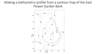
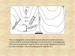
Topographic map A topographic map is a detailed and accurate two-dimensional representation of natural and human-made features on the Earth's surface. The distinctive characteristic of a topographic map is the use of elevation contour lines to show the shape of the Earth's surface.