VOLVO SD77F SINGLE-DRUM ROLLER Service Repair Manual Instant Download
Please open the website below to get the complete manualnn//
Download Presentation

Please find below an Image/Link to download the presentation.
The content on the website is provided AS IS for your information and personal use only. It may not be sold, licensed, or shared on other websites without obtaining consent from the author. Download presentation by click this link. If you encounter any issues during the download, it is possible that the publisher has removed the file from their server.
E N D
Presentation Transcript
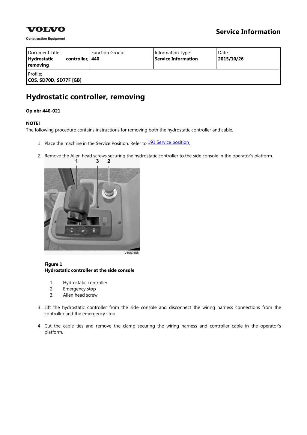
Service Information Document Title: Hydrostatic removing Function Group: 440 Information Type: Service Information Date: 2015/10/26 controller, Profile: COS, SD70D, SD77F [GB] Hydrostatic controller, removing Op nbr 440-021 NOTE! The following procedure contains instructions for removing both the hydrostatic controller and cable. 191 Service position 1. Place the machine in the Service Position. Refer to . 2. Remove the Allen head screws securing the hydrostatic controller to the side console in the operator's platform. Figure 1 Hydrostatic controller at the side console 1. 2. 3. Hydrostatic controller Emergency stop Allen head screw 3. Lift the hydrostatic controller from the side console and disconnect the wiring harness connections from the controller and the emergency stop. 4. Cut the cable ties and remove the clamp securing the wiring harness and controller cable in the operator's platform.
Figure 2 Wiring harnesses and controller cable secured in the operator's platform 1. 2. 3. Clamp Wiring harness connector Cable tie 810 Operator's platform, raising 5. Place the operator's platform in the tilt position. Refer to . 6. Remove the clamps and cable ties securing the controller cable to the underside of the operator's platform. Remove any clamps or cable ties following the cable routing around the frame to the hydrostatic pump. Figure 3 Controller cable routing underneath the operator's platform 1. 2. 3. Controller cable Clamp Clamp 7. Disconnect the controller cable from the hydrostatic pump lever and remove the cable clamp.
Figure 4 Controller cable connection at the hydrostatic pump 8. Carefully remove the hydrostatic controller assembly out of the side console by feeding the controller cable along the frame and out of the machine through the floor of the operator's platform. 9. Secure the controller assembly in a bench vice. Disconnect the cable from the controller by removing the cable clamp and turning the threaded end of the cable out of the control lever link.
https://www.ebooklibonline.com Hello dear friend! Thank you very much for reading. Enter the link into your browser. The full manual is available for immediate download. https://www.ebooklibonline.com
Service Information Document Title: Hydrostatic installing Function Group: 440 Information Type: Service Information Date: 2015/10/26 controller, Profile: COS, SD70D, SD77F [GB] Hydrostatic controller, installing Op nbr 440-022 NOTE! This procedure includes installation and adjustment of the hydrostatic controller and cable which is required if either the controller or cable is replaced. 1. Secure the new controller assembly in a bench vice and connect the cable by turning the threaded rod end of the cable into the control lever linkage. Secure the cable with the clamp to retain it at the controller assembly plate. 2. NOTE! The controller cable must be adjusted at the lever at the hydrostatic pump to the neutral or stop position, so that it has equal travel distance in both directions when the control lever is engaged in the forward or reverse positions. Adjust the hydrostatic controller and cable as follows: a. Place the control lever in the stop position and measure the distance from the end of the cable cap to the center of the pin hole in the cable end clevis. Shift the control lever to the forward position and measure the travel distance of the cable when it is fully extended. Return the lever to the stop position. Shift the control lever to the reverse position and measure the travel distance of the cable when it is fully retracted. Adjust the cable using the threaded rod at the control lever link to make fine adjustments or move the position of the cable clamp plate at the adjustment slots, if necessary. NOTE! The cable must extend and retract equal distance when the control lever is operated from the stop to forward and the stop to reverse positions. b. c. d. e. f. Secure the cable clamp to the controller assembly plate when the cable is adjusted properly. 3. Lift the controller into position at the side console in the operator's platform. Carefully feed the cable through the console and out through the hole in the floor plate of the operator's platform. 4. Place the controller into the side console and connect the wiring harness connectors to the controller and the emergency stop.
Figure 1 Wiring harness connections at the controller side console 5. NOTE! Ensure that the control lever is placed in the stop position. Re-route the cable under the operator's platform and along the frame in the same path to the hydrostatic pump as was previously installed. Secure with the clamps and cable ties, as required. 6. Re-connect the cable end clevis to the lever on the hydrostatic pump and secure the cable with the clamp at the frame. Figure 2 Controller cable routing below the operator's platform 1. 2. 3. Cable Clamp Clamp 810 Operator's platform, lowering 7. Lower the operator's platform back into position. Refer to NOTE! Take care when lowering the operator's platform to ensure the controller cable is routed properly to prevent it from being pinched. . 8. Secure the controller to the side console with the Allen head screws.
Figure 3 Hydrostatic controller at the side console 1. 2. 3. Hydrostatic controller Emergency stop Allen head screw 9. Secure the wiring harness and cable to the operator's platform below the console with the clamp and cable ties, as required. 10. Ensure the control lever is placed in the stop position before starting the engine. Start the engine and test for proper operation of the emergency stop before operating the control lever. 11. Move the machine to a suitable location and test run the machine in both directions of travel to verify proper operation of the hydrostatic controller. 12. Place the machine back in service.
Service Information Document Title: Rear axle drive motor, description Function Group: 441 Information Type: Service Information Date: 2015/10/26 Profile: COS, SD70D, SD77F [GB] Rear axle drive motor, description The rear axle drive motor is mounted directly to the rear drive axle. The rear axle drive motor is a variable displacement bi- directional cartridge motor with a minimum and maximum displacement setting. The motor has a two position electro- hydraulic control which selects minimum or maximum swashplate angle for high and low speeds. Low speed = maximum displacement (maximum swashplate angle); High speed = minimum displacement (minimum swashplate angle).
Figure 1 Rear axle drive motor and components 1. 2. 3. 4. 5. 6. 7. 8. 9. Rear axle drive motor O-ring Adapter Washer Hexagon screw O-ring Flange fitting Fitting Hexagon screw Washer 10.
Service Information Document Title: Drum description Function Group: 441 Information Type: Service Information Date: 2015/10/26 drive motor, Profile: COS, SD70D, SD77F [GB] Drum drive motor, description The drum drive motor is located on the right side of the drum when sitting in the cab. The drum drive motor is a fixed displacement bent axis motor with no swashplate. Two speeds are achieved by oil flow from the hydrostatic pump which in turn drives the planetary. This is controlled by the speed range selector switch.
Figure 1 Drum drive motor and components 1. 2. 3. 4. 5. 6. Drum drive motor Drive plate Drive motor mounting bracket Washer Hexagon screw Washer
7. 8. 9. Allen head screw Split flange Elbow fitting Fitting Adapter Adapter 10. 11. 12.
Service Information Document Title: Hydraulic motor, replacing Function Group: 441 Information Type: Service Information Date: 2015/10/26 Profile: COS, SD70D, SD77F [GB] Hydraulic motor, replacing Op nbr 441-002 Suitable container Vacuum pump Lifting device Removing 191 Service position 1. Place the machine in the Service Position. Refer to . 2. Using a suitable container, drain the oil from the rear axle. 771 Wheel, removing and fitting one 3. Remove the left tyre to allow for easier access to the rear axle motor. Refer to . 4. Disconnect the wiring harness connector from the rear axle motor. 5. Place a suitable container underneath the rear axle motor. NOTICE Always handle oils and other environmentally hazardous fluids in an environmentally safe manner. NOTICE Maintain cleanliness so that dirt doesn't enter the system. 6. Install a suitable vacuum pump at the breather located at the top of the hydraulic oil tank. Refer to 179 Hydraulic oil tank, vacuum-pumping, connecting and disconnecting pump . 7. Disconnect the hydraulic hoses connected at the rear axle motor. Plug and cap the hydraulic hoses to prevent contamination of the hydraulic system. Figure 1 Hydraulic hose connections at the rear axle motor
8. Remove the hexagon screws securing the rear axle motor to the rear axle. WARNING Only use lifting devices with adequate capacity. 9. Pull the rear axle motor out of the mounting flange to disengage the drive splines. Remove the rear axle motor from the machine using a suitable lifting device. Weight of the rear axle motor 50 kg (110 lbs) Installing 10. Using a suitable lifting device, position the new rear axle motor into place at the rear axle. 11. Align the drive splines and install the rear axle motor onto the mounting flange of the rear axle. 12. Secure the rear axle motor with the hexagon screws. Using a suitable locking compound, torque the hexagon screws to specification. 13. Turn the vacuum pump back on and re-connect the hydraulic hoses at the rear axle motor. 14. Disconnect the vacuum pump. 15. Re-connect the wiring harness at the rear axle motor. 771 Wheel, removing and fitting one 16. Re-install the left tyre. Refer to . 173 Rear axle, changing oil 17. Fill the rear axle with hydraulic oil. Refer to . 18. Start the machine and verify proper operation and inspect for leaks. 19. Place the machine back in service.
Service Information Document Title: Drive motor, removing Function Group: Information Type: Service Information Date: 2015/10/26 Profile: COS, SD77F [GB] Drive motor, removing Hydrostatic drum drive motor Op nbr 441-035 Suitable container 191 Service position 1. Place the machine in the service position. Refer to . 2. Place a suitable container below the drum drive motor to collect any oil that may escape. NOTICE Always handle oils and other environmentally hazardous fluids in an environmentally safe manner. Tag and identify the hoses and port locations for proper connection when re-installing the drum drive motor. Disconnect the hoses from the drum drive motor and immediately cap and plug the hose ends and motor port fittings. Figure 1 Drum drive motor and connections 1. 2. 3. Fitting Drum drive motor Hexagon screw NOTICE Maintain cleanliness so that dirt doesn't enter the system. 3. Remove the hexagon screws securing the drum drive motor to the drum drive planetary. 4. Attach the motor to a suitable lifting device. Pull the drum drive motor out of the mounting flange to disengage the drive splines. Remove the motor from the planetary. Weight of the drum drive motor: 27 kg (60 lb)
Suggest: For more complete manuals. Please go to the home page. https://www.ebooklibonline.com If the above button click is invalid. Please download this document first, and then click the above link to download the complete manual. Thank you so much for reading
Service Information Document Title: Drive motor, installing Function Group: Information Type: Service Information Date: 2015/10/26 Profile: COS, SD77F [GB] Drive motor, installing Hydrostatic drum drive motor Op nbr 441-036 1. Transfer all necessary components to the new drum drive motor. Before installing the drum drive motor, inspect the O-ring seal on the mounting flange and replace as required. Clean and prepare the motor mounting surfaces and drive spline for installation and lubricate with clean hydraulic oil. 2. Ensure the inner surfaces, drive spline coupling and mounting flange of the drum drive planetary are cleaned and lubricated with clean hydraulic oil for re-mounting the drum drive motor. Figure 1 Drum drive planetary 1. 2. 3. Planetary drive spline Internal drum drive motor mount surface Drum drive motor flange mount surface 3. Using a suitable lifting device, lift the drum drive motor into position at the planetary. Weight of the drum drive motor 27 kg (60 lbs) Align the shaft drive splines of the drum drive motor with the planetary and push the motor into the planetary. Be sure that the shaft drive splines are fully engaged and seated in position. 4. Secure the drum drive motor to the planetary with the hexagon screws. Using a suitable locking compound, 030 Tightening torque, specifications torque the hexagon screws to specification. Refer to . 5. Re-install the hydraulic hoses to the drum drive motor.
Figure 2 Drum drive motor and connections 1. 2. 3. Fitting Drum drive motor Hexagon screw 173 Drum drive planetary oil level, checking 6. Top up the oil level in the drum drive planetary. Refer to . 7. Start the machine, verify proper operation and inspect for leaks. 8. Place the machine back in service.
https://www.ebooklibonline.com Hello dear friend! Thank you very much for reading. Enter the link into your browser. The full manual is available for immediate download. https://www.ebooklibonline.com

