VOLVO SD45F SOIL COMPACATOR Service Repair Manual Instant Download
Please open the website below to get the complete manualnn//
Download Presentation

Please find below an Image/Link to download the presentation.
The content on the website is provided AS IS for your information and personal use only. It may not be sold, licensed, or shared on other websites without obtaining consent from the author. Download presentation by click this link. If you encounter any issues during the download, it is possible that the publisher has removed the file from their server.
E N D
Presentation Transcript
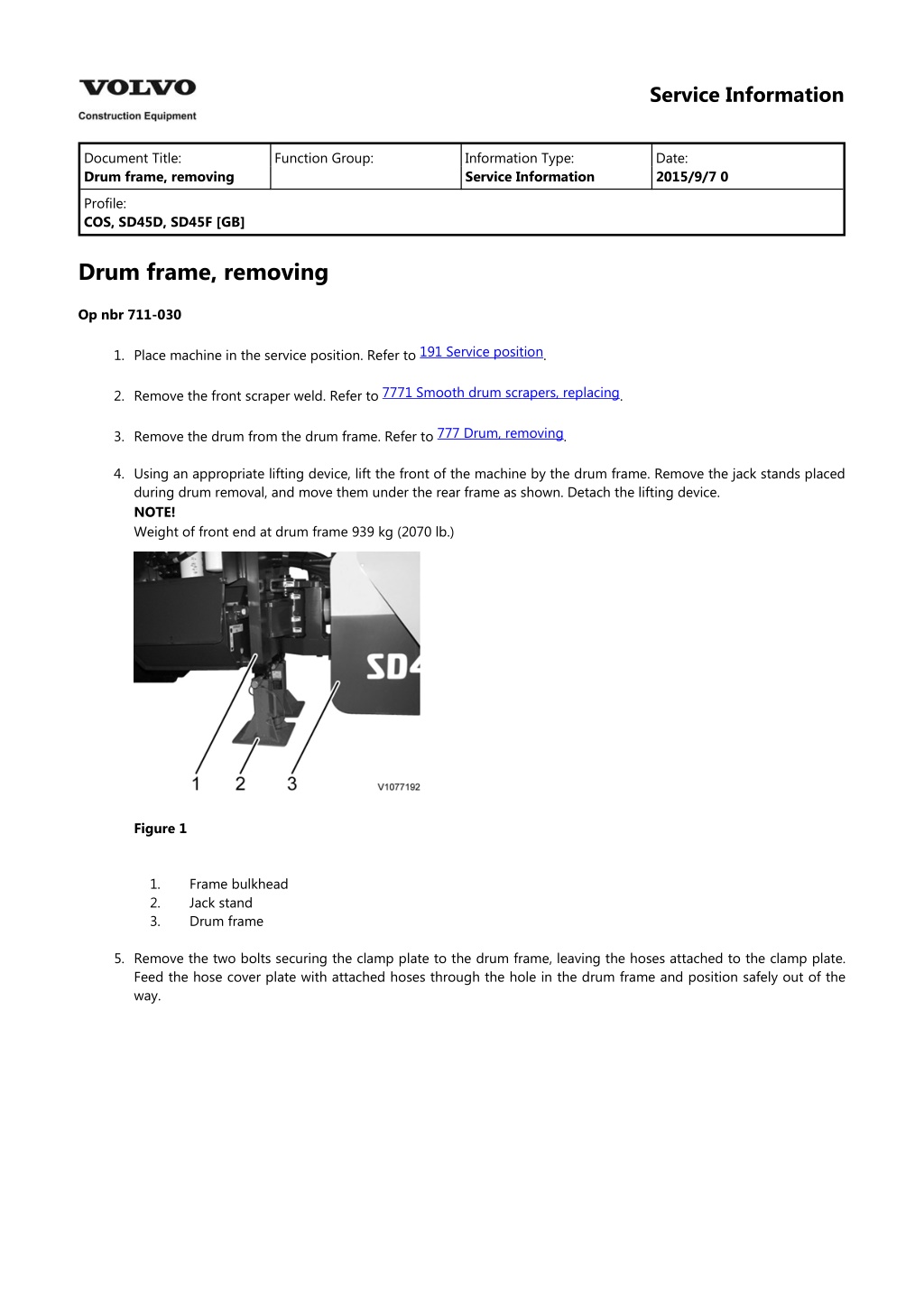
Service Information Document Title: Drum frame, removing Function Group: Information Type: Service Information Date: 2015/9/7 0 Profile: COS, SD45D, SD45F [GB] Drum frame, removing Op nbr 711-030 191 Service position 1. Place machine in the service position. Refer to . 7771 Smooth drum scrapers, replacing 2. Remove the front scraper weld. Refer to . 777 Drum, removing 3. Remove the drum from the drum frame. Refer to . 4. Using an appropriate lifting device, lift the front of the machine by the drum frame. Remove the jack stands placed during drum removal, and move them under the rear frame as shown. Detach the lifting device. NOTE! Weight of front end at drum frame 939 kg (2070 lb.) Figure 1 1. 2. 3. Frame bulkhead Jack stand Drum frame 5. Remove the two bolts securing the clamp plate to the drum frame, leaving the hoses attached to the clamp plate. Feed the hose cover plate with attached hoses through the hole in the drum frame and position safely out of the way.
Figure 2 1. Two (2) bolts to be removed 6. Repeat step 5 with the opposite side of the machine. 7. Remove the bolts and washers securing the lock plate to the swivel. Remove the lock plate form the articulation pin. 8. Secure the drum frame with appropriate lifting straps. Place the straps as shown on the drum frame. Remove the articulation pin and remove the drum frame from the swivel. NOTE! Weight of drum frame 460 kg (1015 lb.) Figure 3 1. Straps shown at approximate balance points on drum frame
Service Information Document Title: Drum frame, installing Function Group: Information Type: Service Information Date: 2015/9/7 0 Profile: COS, SD45D, SD45F [GB] Drum frame, installing Op nbr 711-031 1. Replace the dust seals on the drum frame and inspect the bearing cups and cones. 2. Using an appropriate lifting device, lift the drum frame and position it above the swivel. Slowly lower the drum frame into position, making sure the rear bearing cone does not rotate, and the dust seals do not tear. NOTE! Weight of the drum frame: 460 kg (1015 lb.) Figure 1 V1081070 1. Straps shown at approximate balance points on drum frame 3. Replace the o-ring on the oscillation pin and insert the horizontal oscillation pin through the drum frame into the swivel. Tighten and torque. Refer to 030 Tightening torque, specifications . Remove the lifting device. 4. Apply a high strength thread locking compound and install the lock plate. Tighten and torque. Refer to . 030 Tightening torque, specifications 5. Pull the hoses through the opening of the drum frame. Apply a high strength thread locking compound and install the attached clamp plates to the drum frame with two (2) bolts and washers. 6. Repeat step 5 for the other side of the machine.
https://www.ebooklibonline.com Hello dear friend! Thank you very much for reading. Enter the link into your browser. The full manual is available for immediate download. https://www.ebooklibonline.com
Service Information Document Title: Swivel, removing Function Group: Information Type: Service Information Date: 2015/9/7 0 Profile: COS, SD45D, SD45F [GB] Swivel, removing Op nbr 711-035 191 Service position 1. Place the machine in the service position. Refer to . 7771 Smooth drum scrapers, replacing 2. Remove the front scraper weld. Refer to . 777 Drum, removing 3. Remove the drum from the drum frame. Refer to . 7117 Drum frame, removing 4. Remove the drum frame. Refer to . 5. Remove the hanger assembly connecting the hoses to the main frame to allow for more vertical clearance. Pull the hoses to one side of the machine. 6. Remove the roll pin from the pivot pin. 7. Remove the pivot pin form the swivel and steer cylinder. 8. Remove the lock plate. 9. Place an appropriate floor jack under the swivel and raise until it makes contact with the swivel, but does not lift the machine. Secure the swivel to the floor jack with C clamps. Figure 1 Swivel secured to floor jack with C clamps 10. Remove the oscillation pin from the swivel 11. Remove the articulation lock pin from the service position and separate the swivel from the rear frame.
Service Information Document Title: Swivel, installing Function Group: Information Type: Service Information Date: 2015/9/7 0 Profile: COS, SD45D, SD45F [GB] Swivel, installing Op nbr 711-036 1. Replace the dust seals on the main frame before the swivel is installed. Secure the swivel to an appropriate floor jack with C clamps. 2. Inspect the bearing races, cones and bushings and replace if necessary. 3. Carefully install the swivel to the main frame with a horizontal motion. Be cautious not to rip the dust seals while installing. 4. Install the articulation lock pin in the swivel. Place a new o-ring on the articulation pin and install into the swivel. Tighten and torque. Refer to 030 Tightening torque, specifications 5. Connect the steering cylinder to the swivel with the pivot pin. Secure the pivot pin with the roll pin. 6. Apply a high strength thread locking compound and install the lock plate to the swivel with the two (2) bolts and washers. Refer to . 030 Thread locking compound, application/specifications 030 Tightening torque, specifications . Tighten and torque. Refer to 7. Install the hanger assembly to the main frame. 173 Steering cylinder pins, greasing 8. Grease 173 Swivel joint (horizontal and vertical) pins, greasing the pivot pin and oscillation joint. Refer to and .
Service Information Document Title: Wheel, fitting one Function Group: 771 Information Type: Service Information Date: 2015/9/7 0 removing and Profile: COS, SD45D, SD45F [GB] Wheel, removing and fitting one Op nbr 771-001 11668010 Wheel forklift NOTE! Read the Safety Section before starting the procedure. Wheel, removing 191 Service position 1 1. Place machine in the service position. Refer to . 2. Secure the machine with an appropriate jack stand under the rear end of the machine. Make sure it is positioned correctly and has safe ground support. Figure 1 1. 2. Lifting points Jack stands WARNING Never work under/on machines without using recommended support equipment. NOTE! Before lifting the machine read 191 Safety when lifting and supporting complete machine . 3. Use a wheel forklift and secure the wheel.
Figure 2 Wheel forklift 4. Remove the wheel nuts and wheel from the machine. WARNING Risk of personal injury. Very heavy object. Wheel weight (including fluid): 216 kg (477 lb.) NOTE! When mounting a tyre the qualified person should: Ensure the rim is clean and rust free. The rim must be free of any damage that could prevent proper seating along the bead, or cause improper tyre rotation and premature wear, or affect handling of the machine. Generously lubricate both tyre and rim. WARNING Explosion hazard. Never inflate the tyre to over 2.4 bar (35 psi) to seat beads. Excessive inflation pressure when seating beads may cause the tyre and rim assembly to explode causing severe injury or death. Ensure normal operating pressure is not above 1.1 bar (16 psi). NOTE! Placing water in tyres is an economical means of adding weight to the wheels of the machine. The addition of calcium chloride to the water is recommended to prevent the water from freezing. If a tyre with ballast is replaced the replacement tyre must also contain an equal amount of ballast. Contact a Manufacturer's Authorized Dealer or Distributor for more information on ballasted tyres. Wheel, installing 5. Before reinstalling the wheel to the axle hub, clean the mounting face of the axle and wheel with a wire brush. 6. Reinstall the wheel with the wheel forklift. Wheel weight (including fluid): 216 kg (477 lb.) 030 Wheel, tightening torque 7. Reinstall the wheel nuts. Torque the nuts in a rotating diagonal pattern. Refer to .
Figure 3 Wheel nuts, torque tighten 8. Lower the machine and remove the lifting device and jack stands. 173 Tyres, checking air pressure 9. Check the tyre pressure. Refer to .
Service Information Document Title: Drum eccentric, description 777 Function Group: Information Type: Service Information Date: 2015/9/7 0 Profile: COS, SD45D, SD45F [GB] Drum eccentric, description The drum is equipped with an eccentric weight mounted internally which acts in a centrifugal manner. The purpose of the eccentric is to provide vibration to the drum, which aids in the compaction of the soil. The eccentric can be set to either high or low amplitude by activating the switch in the operator's platform, depending on the conditions of the soil.
Figure 1 Drum eccentric and components 1. 2. 3. 4. 5. Drum drive side journal Eccentric weight - outer Eccentric weight - inner Vibration side drive journal Bearing
6. 7. 8. 9. Splined coupling Washer Hexagon screw Hexagon screw Pin 10.
Service Information Document Title: Drum replacing Function Group: 777 Information Type: Service Information Date: 2015/9/7 0 shock mount, Profile: COS, SD45D, SD45F [GB] Drum shock mount, replacing Op nbr 777-009 Removing the shock mount 191 Service position 1. Place machine in the service position. . 2. Remove the nut and two (2) washers attaching the shock mount to the shock plate. Figure 1 1. 2. 3. Drum frame Shock plate Shock mount 3. Remove the two (2) bolts and washers attaching the shock mount to the carrier plate. The shock mount can now be removed. Installing the shock mount 4. Using an appropriate lifting device, take some weight off the drum frame to allow easier alignment and installation. 5. Slide the shock mount into the horizontal slot on the shock plate. Align the holes at the rear of the shock mount with the threaded holes on the carrier plate. Apply a high strength thread locking compound to the bolts. Tighten and torque. Refer to 030 Tightening torque, specifications . 6. Apply a high strength thread locking compound to the threaded stud on the shock mount. Install the nut and two (2) washers. Tighten and torque. Refer to 030 Tightening torque, specifications .
Service Information Document Title: Drum, removing Function Group: 777 Information Type: Service Information Date: 2015/9/7 0 Profile: COS, SD45D, SD45F [GB] Drum, removing Op nbr 777-001 191 Service position 1. Place machine in the service position. Refer to . 7771 Smooth drum scrapers, replacing 2. Remove the scraper from the machine. Refer to . 3. Using an appropriate lifting device, lift the front end of the machine high enough to place a set of jack stands under the front of the drum frame as shown. a. Adjust the jack stands so approximately 5 cm (2 in.) exists between the bottom of the drum and the ground. Do not remove the weight from the lifting device to ensure that the drum does not fall after the hardware is removed. b. Figure 1 Proper placement of jack stands with drum attached to lifting device NOTE! Weight of the front end of the machine 2216 kg (4885 lb.) NOTICE It is very important to keep the hydraulic system free from any impurities, as these can cause abnormal wear and may lead to expensive downtime. Greatest possible cleanliness should be maintained during all handling of hydraulic components and hydraulic oil. 4. Clean, identify and remove the hoses from the vibration motor. Cap or plug all hoses and adapters. 5. Clean, identify and remove the hoses from the drive motor. Cap or plug all hoses and adapters. 6. Remove the six (6) bolts attaching the hose cover plate to the drum frame. With the hoses still clamped to the hose cover plate, pull the hoses through the hole in the drum frame.
Figure 2 Hose cover plate removed with hoses attached 7. Repeat step 5 with the opposite side of the machine. WARNING The work involves handling heavy components - failure to stay alert may result in severe crushing injuries. 8. Remove the drum from the drum frame. a. b. Remove the eight (8) nuts and washers attaching the drum to the carrier plate and torque hub. Remove the eight (8) bolts and washers from the drum frame. NOTE! Retain the shims from the carrier side of the drum. c. d. With an appropriate lifting device, lift the drum from the machine in a vertical direction. Place the drum on a suitable flat surface away from the machine for service, taking care to block the drum from any rolling motion. NOTE! Weight of the assembled drum 1406 kg (3100 lb.) NOTE! All drums will have a shim pack on the carrier side of the drum. These can be reused, but may not require the same amount as removed from the machine.
Service Information Document Title: Drum, installing Function Group: 777 Information Type: Service Information Date: 2015/9/7 0 Profile: COS, SD45D, SD45F [GB] Drum, installing Op nbr 777-002 WARNING The work involves handling heavy components - failure to stay alert may result in severe crushing injuries. 1. Using an appropriate lifting device, lower the drum into the drum frame until the four (4) holes in the drum frame align with the four (4) holes in the torque hub drive plate. NOTE! Weight of the assembled drum is 1406 kg (3100 lb.) 2. Apply a high strength thread locking compound to the four (4) bolts. Insert bolts and washers through the drum frame and torque hub and hand tighten a nut with washer on the back side of the torque hub on each bolt. Do not tighten at this time. 3. Make adjustments with the lifting device until the holes in the carrier align with the holes in the drum frame. Ensure the top of the carrier is facing up by verifying the filtered vent breather and grease fitting are facing the top of the drum. Place a bolt into each bottom hole to prevent the carrier from rotating. 4. Using a pry bar, open the space between the top front carrier shock plate and the drum frame. Install the shim pack, aligning the holes in the shims with the holes in the drum frame and carrier shock plate. Apply high strength thread locking compound to the bolt. Insert a bolt and washer through the drum frame, shims and shock plate. Remove the pry bar, and install a nut and washer on the back of the bolt. Do not tighten at this time. 5. Move the pry bar to the bottom front carrier shock plate and apply pressure. Allow the shims to rotate on the top bolt until they align with the holes in the drum frame and carrier shock plate. Apply high strength thread locking compound to the bolt. Insert a bolt and washer through the drum frame, shims and shock plate. Remove the pry bar, and install a nut and washer on the back of the bolt. Do not tighten and torque at this time. 6. Repeat steps 4 and 5 with the rear carrier shock mount. 7. Using the lifting device, lift the front end of the machine by the drum and remove the jack stands under the front of the drum frame. Remove the appropriate lifting device from the drum. NOTE! Weight of front end of the machine 2216 kg (4885 lb.) 8. With the drum no longer suspended, tighten and torque the eight (8) bolts attaching the drum to the drum frame. Refer to . 030 Tightening torque, specifications 7771 Smooth drum scrapers, replacing 9. Install the front scraper. Refer to . 7774 Vibration motor, installing 10. Install the vibration motor. Refer to NOTICE It is very important to keep the hydraulic system free from any impurities, as these can cause abnormal wear and may lead to expensive downtime. Greatest possible cleanliness should be maintained during all handling of hydraulic components and hydraulic oil. .
11. Clean, identify, and connect the hoses on the torque hub. Inspect the o-rings and replace if necessary. Tighten and torque. Refer to 030 Hydraulic connections, tightening torques . 12. Align the holes of the hose cover plate with the threaded holes on the drum frame. Apply a medium strength thread locking compound. Refer to plates to the drum frame with the six (6) bolts and washers. Repeat this step for the opposite side of the machine. 030 Thread locking compound, application/specifications . Attach the hose cover 173 Hydraulic oil level, checking 13. Add hydraulic fluid to the hydraulic tank if needed. Refer to . 14. Start the machine and check for leaks.
Suggest: For more complete manuals. Please go to the home page. https://www.ebooklibonline.com If the above button click is invalid. Please download this document first, and then click the above link to download the complete manual. Thank you so much for reading
Service Information Document Title: Carrier, removing Function Group: 777 Information Type: Service Information Date: 2015/9/7 0 Profile: COS, SD45D, SD45F [GB] Carrier, removing Op nbr 777-025 191 Service position 1. Place machine in the service position. Refer to . 2. Remove the drum. Refer to 777 Drum, removing NOTE! Place a mark indicating the top of the carrier for easier installation. 173 Drum carrier, changing oil 3. Drain the oil from the carrier. Refer to . 173 Drum eccentric, changing oil 4. Drain the eccentric oil from the drum. Refer to . 7774 Vibration motor, removing 5. Remove the vibration motor from the carrier assembly. Refer to NOTE! The next step requires two (2) technicians. One technician will guide the carrier off the bearings with the rods. The other technician will use the lifting device to remove the weight from the bearings, allowing the removal of the carrier with minimal pulling force. . 6. Place an appropriate clevis in each of the top holes of the shock plates. Connect an appropriate lifting device to the carrier. Place a 1.5 m (5 ft.) steel rod in each of the bottom holes in the shock plate. NOTE! The weight of the carrier assembly is 153 kg (337 lb.)
Figure 1 1. 2. Place clevis in this hole Place rod in this hole 7. Place the carrier assembly on a suitable working surface. 8. Remove the o-ring and oil seal from the back of the carrier and discard.
https://www.ebooklibonline.com Hello dear friend! Thank you very much for reading. Enter the link into your browser. The full manual is available for immediate download. https://www.ebooklibonline.com

