VOLVO EC460C LD EC460CLD EXCAVATOR Service Repair Manual Instant Download
Please open the website below to get the complete manualnn//
Download Presentation

Please find below an Image/Link to download the presentation.
The content on the website is provided AS IS for your information and personal use only. It may not be sold, licensed, or shared on other websites without obtaining consent from the author. Download presentation by click this link. If you encounter any issues during the download, it is possible that the publisher has removed the file from their server.
E N D
Presentation Transcript
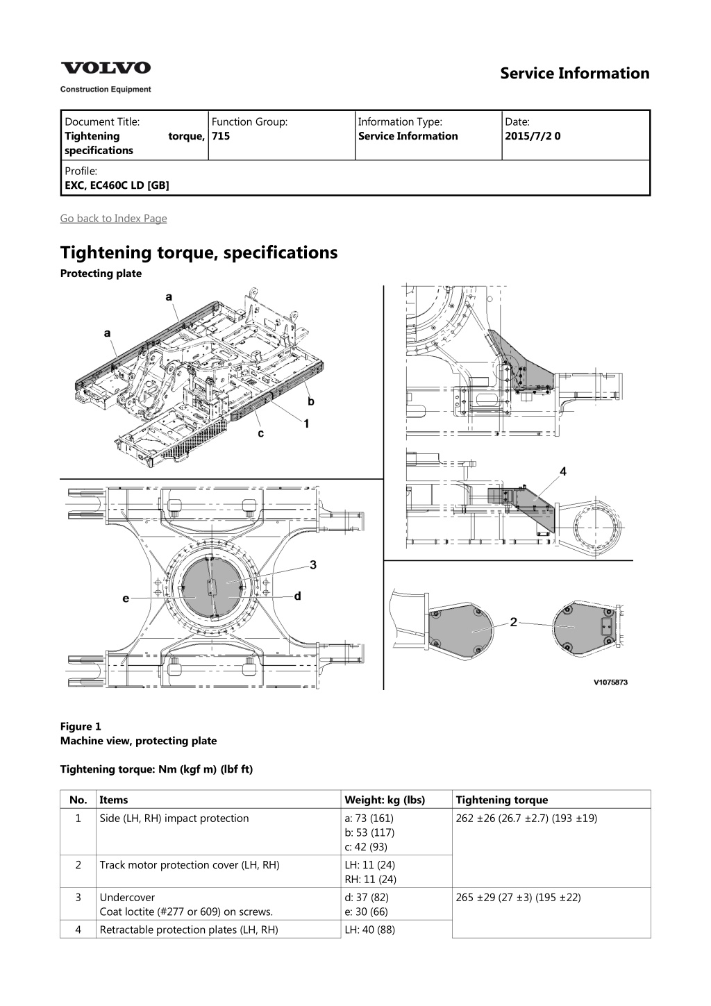
Service Information Document Title: Tightening specifications Function Group: 715 Information Type: Service Information Date: 2015/7/2 0 torque, Profile: EXC, EC460C LD [GB] Go back to Index Page Tightening torque, specifications Protecting plate Figure 1 Machine view, protecting plate Tightening torque: Nm (kgf m) (lbf ft) No. 1 Items Side (LH, RH) impact protection Weight: kg (lbs) a: 73 (161) b: 53 (117) c: 42 (93) LH: 11 (24) RH: 11 (24) d: 37 (82) e: 30 (66) LH: 40 (88) Tightening torque 262 26 (26.7 2.7) (193 19) 2 Track motor protection cover (LH, RH) 3 Undercover Coat loctite (#277 or 609) on screws. Retractable protection plates (LH, RH) 265 29 (27 3) (195 22) 4
Service Information Document Title: Tightening specifications Function Group: 715 Information Type: Service Information Date: 2015/7/2 0 torque, Profile: EXC, EC460C LD [GB] Go back to Index Page Tightening torque, specifications Boom cylinder protecting guard, Demolition standard Figure 1 Boom cylinder protecting guard Tightening torque No. Items Weight: kg (lbs) Tightening torque Nm (kgf m) (lbf ft) 262 26.5 (26.7 2.7) (193 19.5) 1 2 3 4 5 a Boom cylinder protecting guard Clamp-lower Clamp-upper Mounting screws Mounting screws 435 mm (17.13 inch) 79.7 (175.7) 1.4 (3.1) 8.2 (18.1) 8 EA 8 EA
b c 735 mm (28.94 inch) 318 mm (12.52 inch) NOTE! Mounting screws. Apply Loctite #277 or equivalent locking fluid.
https://www.ebooklibonline.com Hello dear friend! Thank you very much for reading. Enter the link into your browser. The full manual is available for immediate download. https://www.ebooklibonline.com
Service Information Document Title: Protecting description Function Group: 715 Information Type: Service Information Date: 2015/7/2 0 plate, Profile: EXC, EC460C LD [GB] Protecting plate, description Bucket cylinder protecting guard, Demolition Figure 1 Protecting guard, bucket cylinder (standard) Gap and shims Items Position GAP 1 GAP 2 GAP 3 GAP 4 A B C Gap clearances: mm (inch) Minimum +0.5 (0.01969) +2.0 (0.07874) +0.5 (0.01969) +0.5 (0.01969) 111 11 Nm (11.3 1.1 kgf m) (82 8 lbf ft) 262 26 Nm (26.7 2.7 kgf m) (193 19 lbf ft) 511.9 50.9 Nm (52.2 5.2 kgf m) (376.9 37.5 lbf ft) Thick shims (1.0 t) Quantity 2 2 Thick shims (0.5 t) Quantity 1 1 Maximum +2.5 (0.09843) +3.0 (0.11811) +1.5 (0.05906) +1.5 (0.05906) NOTE! The item #4 and #5 before assembly coated grease on the hole inside.
Service Information Document Title: Boom cylinder protecting guard, removal Function Group: 715 Information Type: Service Information Date: 2015/7/2 0 Profile: EXC, EC460C LD [GB] Go back to Index Page Boom cylinder protecting guard, removal Op nbr 715-019 091 Service positions 1. Park the machine in the service position B, see . Figure 1 Position, boom cylinders 2. Raise boom cylinders (1), to Vertical position and stop engine. 3. Install I-bolt and sling guard (2) securely with a hoist. NOTE! Guard weight: 80 kg (176 lbs) WARNING The parts are heavy. Take appropriate safety cautions when handling them. 4. Remove screws (3) and guard (2).
Figure 2 Remove, guard 5. Remove screws (4) and clamps (5). Figure 3 Remove, clamp
Service Information Document Title: Boom cylinder protecting guard, removal Function Group: 715 Information Type: Service Information Date: 2015/7/2 0 Profile: EXC, EC460C LD [GB] Go back to Index Page Boom cylinder protecting guard, removal Op nbr 715-019 091 Service positions 1. Park the machine in the service position B, see . Figure 1 Position, boom cylinders 1. Boom cylinders 2. Sling guard 2. Raise boom cylinders, to Vertical position and stop engine. 3. Install the I-bolt and sling guard securely with a hoist. NOTE! Guard weight. See 715 Tightening torque, specifications . WARNING The parts are heavy. Take appropriate safety cautions when handling them. 4. Remove the screws and guard.
Figure 2 Remove, guard (2) and screws (3) 5. Remove the screws and clamps. Figure 3 Remove, clamp (5) and screws (4)
Service Information Document Title: Boom cylinder protecting guard, installation Function Group: 715 Information Type: Service Information Date: 2015/7/2 0 Profile: EXC, EC460C LD [GB] Go back to Index Page Boom cylinder protecting guard, installation Op nbr 715-020 091 Service positions 1. Park the machine in the service position B, see . Figure 1 Marking, clamp position a. b. 435 mm (17 inch) 735 mm (29 inch) 2. Raise boom cylinders (1), to Vertical position and stop engine. 3. Mark clamp location on each the boom cylinder (1). 4. Install screws (3) and clamps (2), don't over tighten the clamps (2).
Figure 2 Install, clamp 5. Sling guard (4) securely with a hoists and install screws (5). Figure 3 Install, guard NOTE! Apply loctite on screws (5). NOTE! Guard weight: 80 kg (176 lbs) Tightening torque: 262 26 Nm (193 19 lbf ft) WARNING The parts are heavy. Take appropriate safety cautions when handling them. 6. Before installing screws (6) apply loctite.
Figure 4 Install, clamp screw NOTE! Tightening torque: 262 26 Nm (193 19 lbf ft) 7. Check for interference of guard by operating the boom cylinders.
Service Information Document Title: Boom cylinder protecting guard, installation Function Group: 715 Information Type: Service Information Date: 2015/7/2 0 Profile: EXC, EC460C LD [GB] Go back to Index Page Boom cylinder protecting guard, installation Op nbr 715-020 091 Service positions 1. Park the machine in the service position B, see . Figure 1 Marking, clamp position a. b. XXX mm (XX inch) XXX mm (XX inch) NOTE! See 715 Tightening torque, specifications . 2. Raise boom cylinders, to Vertical position and stop engine. 3. Mark clamp location on each the boom cylinder. 4. Install the screws and clamps, don't over tighten the clamps.
Suggest: For more complete manuals. Please go to the home page. https://www.ebooklibonline.com If the above button click is invalid. Please download this document first, and then click the above link to download the complete manual. Thank you so much for reading
Figure 2 Install, clamp 2. Clamps 3. Screws 5. Sling guard securely with a hoists and install the screws. Figure 3 Install, guard 4. Sling guard 5. Screws NOTE! Apply loctite on screws (5). NOTE! Guard weight and tightening torque. See 715 Tightening torque, specifications . WARNING The parts are heavy. Take appropriate safety cautions when handling them. 6. Before installing screws apply loctite.
Figure 4 Install, clamp screw (6) NOTE! Tightening torque. See 715 Tightening torque, specifications . 7. Check for interference of guard by operating the boom cylinders.
https://www.ebooklibonline.com Hello dear friend! Thank you very much for reading. Enter the link into your browser. The full manual is available for immediate download. https://www.ebooklibonline.com


