Using Low-cost Stepper Motors for Dobby Mechanism

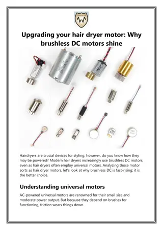
Using Low-cost Stepper Motors
To Create a Dobby Mechanism
Motor
1.75” square
Vertical view
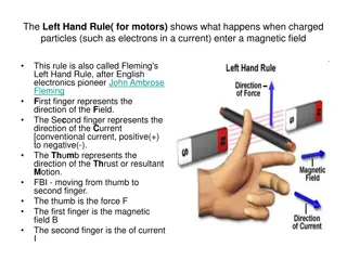
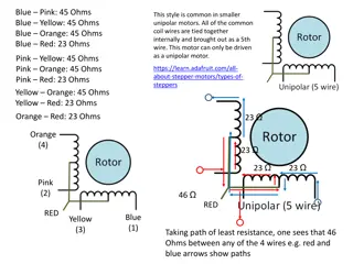
Stepper motor requirements – Loom :
•
Weight to lift-
•
Weight of 8 shafts:
•
2.6 Kg (raw weight)
•
~5 Kg (with warp tension)
•
Per Shaft @ 8 shafts ~0.6 Kg per shaft
•
Lever arm to lift weight-
•
5 mm shaft on motor (5/16”)
•
1 mm cord diameter
•
~8 mm shaft diameter (with tape)
•
Lever arm ~ 5 mm = 0.5 cm
•
Approximate torque requirement:
•
Torque = 0.6 Kg * 0.5 cm
= 0.3 Kg-cm (lifting power)
Motors:
•
characterized by “Holding Torque”, not dynamic lifting power
•
Maximum rotational speed not specified
•
Nominal motor de-rating factor: x10 =
~3 Kg-cm (30Ncm)
•
Price consideration: Nominal $100 for project, $50 for 10
motors, ~ $5 - $8 per motor
Search for Stepper motors:
•
NEMA 17 (NEMA 23?) footprint
•
Over 3 Kg-cm torque
•
6 wire (to simplify control electronics)
•
Less than .5 Amp per phase @ 12VDC
Blk & Wht to +12
Red/grn yel/blu to drivers
(Coil centers actually white & Yellow)
Position sensors/sensor mux (?)
6 Wire Motors (12V to ground switching):
ULN2003A Darlington drivers (7 channel )
•
.5A/channel
•
$0.51 per part
8 motors * 4 channels per = 32 driver channels
32/7 = 5 ULN2003A packages ($3.57)
Shaft
4 Wire Motors (full voltage reversal):
L293d 4 channel drivers.6 A/channel
•
$3.91 per part
8 motors * 4 channels per = 32 driver channels
32/4 = 8 L293d packages ($31.28)
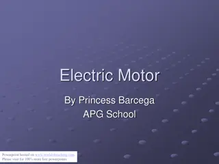
Total weight – 8 shafts
(Scale resting on lower rails of castle)
Lever arm to raise shafts: 5mm shaft
+ 12” tape to increase shaft diameter
Total width of 8 shafts ~3”
0.42” spacing between shafts
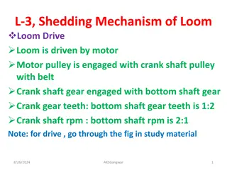
Assembled Left Side
Shaft motors 2,4,6,8
Assembled Right Side
With power & USB connections
Shaft Motors 1,3,5,7
Interior Right Side
(Ends of Shaft Rods 1,3,5,7
In holes in right side)
Black threads connect Weaving
shafts to rod, Loop fits over screw head
for ease of removal
Blue tape on rods increases
diameter, utilizing reserve
torque in motors to reduce
number of rotations (and time)
required to lift shafts
¼” collars on 5/16” rod hold
connecting thread to rod,
easy to adjust for length &
position
Right
USB
Footswitch
12V
Left
This project explores the utilization of low-cost stepper motors to create a dobby mechanism for a loom. It details the stepper motor requirements, including weight to lift and lever arm dimensions. The project also considers motor options, pricing, and control electronics, aiming for an efficient and cost-effective solution. The provided images offer insights into the total weight of the shafts, assembly configurations, and power connections. With a focus on NEMA 17 stepper motors and driver options, this endeavor showcases a budget-friendly approach to implementing a dobby mechanism.

Download Presentation

Please find below an Image/Link to download the presentation.
The content on the website is provided AS IS for your information and personal use only. It may not be sold, licensed, or shared on other websites without obtaining consent from the author.If you encounter any issues during the download, it is possible that the publisher has removed the file from their server.
You are allowed to download the files provided on this website for personal or commercial use, subject to the condition that they are used lawfully. All files are the property of their respective owners.
The content on the website is provided AS IS for your information and personal use only. It may not be sold, licensed, or shared on other websites without obtaining consent from the author.
E N D
Presentation Transcript
Using Low-cost Stepper Motors To Create a Dobby Mechanism
Stepper motor requirements Loom : Weight to lift- Weight of 8 shafts: 2.6 Kg (raw weight) ~5 Kg (with warp tension) Per Shaft @ 8 shafts ~0.6 Kg per shaft Lever arm to lift weight- 5 mm shaft on motor (5/16 ) 1 mm cord diameter ~8 mm shaft diameter (with tape) Lever arm ~ 5 mm = 0.5 cm Approximate torque requirement: Torque = 0.6 Kg * 0.5 cm = 0.3 Kg-cm (lifting power) Motors: characterized by Holding Torque , not dynamic lifting power Maximum rotational speed not specified Nominal motor de-rating factor: x10 = ~3 Kg-cm (30Ncm) Price consideration: Nominal $100 for project, $50 for 10 motors, ~ $5 - $8 per motor Search for Stepper motors: NEMA 17 (NEMA 23?) footprint Over 3 Kg-cm torque 6 wire (to simplify control electronics) Less than .5 Amp per phase @ 12VDC Vertical view Motor 1.75 square 4 x 26.75 base 0.42 spacing between shafts (8 shafts / 3 ) Shaft 6 Wire Motors (12V to ground switching): ULN2003A Darlington drivers (7 channel ) .5A/channel $0.51 per part 8 motors * 4 channels per = 32 driver channels 32/7 = 5 ULN2003A packages ($3.57) 4 Wire Motors (full voltage reversal): L293d 4 channel drivers.6 A/channel $3.91 per part Type 42BYGH404 (NEMA 17 footprint) 1.65 x 1.65 x 1.57 (42.4x42.3x72 cm) 3.4 kg-cm (47.2 oz-in) .4A per phase ~ $6 per (Summer of 2018) https://www.circuitspecialists.com/nema_17_stepper_motor_42bygh404.html?otaid=gpl&gclid=Cj0KCQjwjrvpBRC0ARIsAFrFuV8v7XcrsvspC- rLUqVF1CWTetYBij41v3zOubxWgQV1JUICdI5XC2QaAiWJEALw_wcB Blk & Wht to +12 Red/grn yel/blu to drivers (Coil centers actually white & Yellow) Position sensors/sensor mux (?) 8 motors * 4 channels per = 32 driver channels 32/4 = 8 L293d packages ($31.28)
Total weight 8 shafts (Scale resting on lower rails of castle) Lever arm to raise shafts: 5mm shaft + 12 tape to increase shaft diameter Total width of 8 shafts ~3 0.42 spacing between shafts Blue tape on rods increases diameter, utilizing reserve torque in motors to reduce number of rotations (and time) required to lift shafts collars on 5/16 rod hold connecting thread to rod, easy to adjust for length & position Assembled Left Side Shaft motors 2,4,6,8 Assembled Right Side With power & USB connections Shaft Motors 1,3,5,7 Interior Right Side (Ends of Shaft Rods 1,3,5,7 In holes in right side) Black threads connect Weaving shafts to rod, Loop fits over screw head for ease of removal
Right 12V USB Footswitch