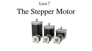
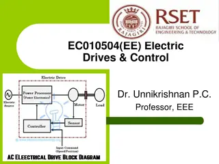
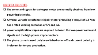
Stepper Motors: Precision Control & Applications
Stepper motors are specialized motors used for precise motion control in various applications such as printers, robotics, and machine tools. They rotate in discrete steps in response to electrical pulses without requiring a feedback system, making them ideal for digital control systems. These motors have different types and can follow signals rapidly, with power ratings up to several horsepower. Variable reluctance and permanent magnet stepper motors are commonly used, each with unique characteristics and applications. Basic operating principles and circuits for stepper motors are also explained.

Download Presentation

Please find below an Image/Link to download the presentation.
The content on the website is provided AS IS for your information and personal use only. It may not be sold, licensed, or shared on other websites without obtaining consent from the author.If you encounter any issues during the download, it is possible that the publisher has removed the file from their server.
You are allowed to download the files provided on this website for personal or commercial use, subject to the condition that they are used lawfully. All files are the property of their respective owners.
The content on the website is provided AS IS for your information and personal use only. It may not be sold, licensed, or shared on other websites without obtaining consent from the author.
E N D
Presentation Transcript
Stepper Motors stepper motors are special motors which rotate in discrete steps and used when motion and position have to be precisely controlled. It rotates by a specific number of degrees in response to an input electrical pulse. Typical step sizes are 20, 2.50, 50, 7.50, and 150for each electrical pulse.
Applications: The stepper motor is used in digital control systems. A train of pulses is made to turn the shaft of the motor by steps. Neither a position sensor nor a feedback system is normally required for the stepper motors to make the output response follow the input command. Typical applications of stepper motors requiring incremental motion are printers, tape drives, disk drives, machine tools, process control systems, X Y plotters, and robotics.
Stepper motors have been built to follow signals as rapid as 1200 pulses per second with power ratings up to several horsepower. Typical resolution of commercially available stepper motors ranges from several steps per revolution to as many as 400 steps per revolution and even higher. Two types of stepper motors are widely used: (1) the variable-reluctance type . (2) the permanent magnet type.
Variable Reluctance Stepper Motor : 1) single-stack type . 2) multiple-stack type. Single-Stack Stepper Motor The stator phases are excited with dc current in proper sequence. A reluctance torque is generated because of the tendency of the rotor to align itself along the direction of the resultant flux. The following figures illustrate operating modes of stepper motor for 450 step.
When winding A is excited, the rotor aligns with the axis of phase A.
Both windings A and B are excited. The rotor aligns itself with the resultant flux and moves 45 0 in the clockwise direction.
When winding B is excited, the rotor aligns with the axis of phase B. Note that: the direction of rotation can be reversed by reversing the sequence of switching the windings, that is, A, A + D, D, D + C, etc.
A multipole rotor construction is required in order to obtain smaller step sizes. if the windings are excited in the sequence A, A+ B, B, B + C, C, the rotor rotates in steps of 150in the anticlockwise direction. Construction of a 4-phase, 6-pole stepper motor
Multistack Stepper Motor : Multistack variable-reluctance-type stepper motors are widely used to give smaller step sizes. The motor is divided along its axial length into magnetically isolated sections ("stacks"), and each of these sections can be excited by a separate winding ("phase"). Three-phase arrangements are most common, but motors with up to seven stacks and phases are available.
Cross section of a three-stack, variable-reluctance stepper motor parallel to the shaft
Example: Teeth position in a 4-pole, . 3- stack, Variable reluctance stepper motor Phase A excited. Rotor and stator teeth are aligned.
a)The rotor teeth in each stack are aligned. b) The stator teeth have different orientation between stacks. c) when stack A is energized, the rotor and stator teeth in stack A are aligned. Developed diagram for rotor and stator teeth for phase A excitation
Number of steps per revolution : Let x be the number of rotor teeth and N the number of stacks or phases. Then : Number of steps per revolution is: Typical step sizes for the multistack variable-reluctance stepping motor are in the range 2 to 15 degrees.
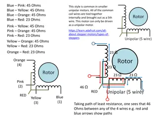
PERMANENT MAGNET STEPPER MOTOR: The permanent magnet stepper motor has a stator construction similar to that of the single-stack variable-reluctance type. The rotor poles align with two stator teeth (or poles) according to the winding excitation. The current polarity is important because it decides the direction in which the motor will move.
Variable Reluctance Stepper motor Permanent magnet Stepper motor item Inertia low high acceleration high low maximum step rate 1200 pulses / second 300 pulses / second torque / amp. of stator current low high step size small (2 to 15 ) Large (30 to 90 )
Hybrid stepper motors: The rotor has an axial permanent magnet at the middle and ferromagnetic teeth at the outer sections. Smaller step sizes can be obtained from these motors, but they are more expensive than the variable-reluctance type stepper motors.
Effect of inertia : In the figure shown, when the switches are closed in the sequence A, B, C the motor rotates ccw in 60 0 steps. The following cases are considered: a) Small load, small damping operation: In moving from pole 1 to pole 2, the rotor oscillates around its 60 0 position before coming to rest. The speed is zero whenever Elementary stepper motor the rotor reaches the limit of its overshoot.
b) High inertia, less friction operation: The overshoot will become greater . The rotor takes longer to settle down.
c) High inertia load, large friction operation The damping can be increased using eddy current brake or viscous damper. The oscillations are damped if the friction increases.
Effect of mechanical loading (low inertia , small damping): The overshoot becomes smaller. The oscillations are damped more quickly. Large settling time.
Graph of current pulses, angular position, and speed during the first four steps
Torque versus current: pull-over torque: The torque that the motor exerts when it moves from one step to another. At rest: A holding current must continue to flow in the last winding that was excited so that the rotor remains locked in place.
Slew speed: A stepper motor is called to run with the slew speed if it runs at uniform speed without startingand stopping at every step. When the motor runs with the slew speed, it can carry greater load. Curve 1: start-stop curve with only stepper motor inertia. Curve 2: start-stop curve with additional load inertia. Curve 3: slewing curve.


The rotor teeth in each")


 High inertia, less friction operation:")
 High inertia load, large friction operation")
:")