Understanding Wave Optics Principles

Explore electromagnetic waves, wavefronts, Huygens' principle, reflection, and refraction of light based on these principles. Learn about the behavior of wavefronts in mirrors, lenses, and prisms, as well as coherent sources, interference, and the Young's double-slit experiment. Dive into the world of colors in thin films and grasp the essential concepts in wave optics.

Download Presentation

Please find below an Image/Link to download the presentation.
The content on the website is provided AS IS for your information and personal use only. It may not be sold, licensed, or shared on other websites without obtaining consent from the author. Download presentation by click this link. If you encounter any issues during the download, it is possible that the publisher has removed the file from their server.
E N D
Presentation Transcript
WAVE OPTICS - I 1. Electromagnetic Wave 2. Wavefront 3. Huygens Principle 4. Reflection of Light based on Huygens Principle 5. Refraction of Light based on Huygens Principle 6. Behaviour of Wavefront in a Mirror, Lens and Prism 7. Coherent Sources 8. Interference 9. Young s Double Slit Experiment 10.Colours in Thin Films
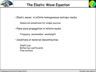
Electromagnetic Wave: Y E0 0 X B0 Z 1. Variations in both electric and magnetic fields occur simultaneously. Therefore, they attain their maxima and minima at the same place and at the same time. 2. The direction of electric and magnetic fields are mutually perpendicular to each other and as well as to the direction of propagation of wave. 3. The speed of electromagnetic wave depends entirely on the electric and magnetic properties of the medium, in which the wave travels and not on the amplitudes of their variations. Wave is propagating along X axis with speed c = 1 / 0 0 For discussion of optical property of EM wave, more significance is given to Electric Field, E. Therefore, Electric Field is called light vector .
Wavefront: A wavelet is the point of disturbance due to propagation of light. A wavefront is the locus of points (wavelets) having the same phase of oscillations. A line perpendicular to a wavefront is called a ray . Cylindrical Wavefront from a linear source Spherical Wavefront from a point source Plane Wavefront Pink Dots Wavelets Blue Envelope Wavefront Red Line Ray
Huygens Construction or Huygens Principle of Secondary Wavelets: ..... . . .. . . . . S . . . . New Wave- front (Plane) New Wavefront (Spherical) (Wavelets - Red dots on the wavefront) 1. Each point on a wavefront acts as a fresh source of disturbance of light. 2. The new wavefront at any time later is obtained by taking the forward envelope of all the secondary wavelets at that time. Note: Backward wavefront is rejected. Why? Amplitude of secondary wavelet is proportional to (1+cos ). Obviously, for the backward wavelet = 180 and (1+cos ) is0.
Laws of Reflection at a Plane Surface (On Huygens Principle): If c be the speed of light, t be the time taken by light to go from B to C or A to D or E to G through F, then N N t =EF FG c D B + E G c r i i r X FC sin r c Y AF sin i c A C + t = F AB Incident wavefront CD Reflected wavefront XY Reflecting surface AC sin r + AF (sin i sin r) c t = For rays of light from different parts on the incident wavefront, the values of AF are different. But light from different points of the incident wavefront should take the same time to reach the corresponding points on the reflected wavefront. So, t should not depend upon AF. This is possible only if sin i sin r = 0. i = r i.e. sin i = sin r or
Laws of Refraction at a Plane Surface (On Huygens Principle): If c be the speed of light, t be the time taken by light to go from B to C or A to D or E to G through F, then N N B Rarer c, 1 E i t =EF FG v i C F X Y + r A c Denser rv, 2 G FC sin r v AF sin i c D + t = AC sin r v + AF ( sin i -sinr ) AB Incident wavefront CD Refracted wavefront XY Refracting surface t = c v For rays of light from different parts on the incident wavefront, the values of AF are different. But light from different points of the incident wavefront should take the same time to reach the corresponding points on the refracted wavefront. So, t should not depend upon AF. This is possible only sin i -sin r or sin i =sin r sin i= c if or = = 0 c v c v v sin r
Behaviour of a Plane Wavefront in a Concave Mirror, Convex Mirror, Convex Lens, Concave Lens and Prism: C A A C D B B D Concave Mirror Convex Mirror C A A C D B B Convex Lens Concave Lens D AB Incident wavefront CD Reflected / Refracted wavefront
A C D B Prism Prism AB Incident wavefront CD Refracted wavefront Coherent Sources: Coherent Sources of light are those sources of light which emit light waves of same wavelength, same frequency and in same phase or having constant phase difference. Coherent sources can be produced by two methods: 1. By division of wavefront (Young s Double Slit Experiment, Fresnel s Biprism and Lloyd s Mirror) 2. By division of amplitude (Partial reflection or refraction)
Interference of Waves: Bright Band E1 +E2 E1 Dark Band E2 S1 S2 Bright Band Dark Band Constructive Interference E = E1 +E2 E1 Bright Band E1 -E2 E2 Crest Trough Bright Band Dark Band Destructive Interference E = E1 -E2 1st Wave (E1) 2nd Wave (E2) Resultant Wave Reference Line The phenomenon of one wave interfering with another and the resulting redistribution of energy in the space around the two sources of disturbance is called interference of waves.
Theory of Interference of Waves: The waves are with same speed, wavelength, frequency, time period, nearly equal amplitudes, travelling in the same direction with constant phase difference of . E1 = a sin t E2 = b sin ( t + ) is the angular frequency of the waves, a,b are the amplitudes and E1, E2 are the instantaneous values of Electric displacement. Applying superposition principle, the magnitude of the resultant displacement of the waves is E = E1 +E2 E = a sin t + b sin ( t + ) E = (a + b cos ) sin t + b sin cos t a + b cos = A cos Putting (where E is the resultant displacement, A is the resultant amplitude and is the resultant phase difference) A sin b sin b sin = A sin b A We get E = A sin ( t + ) a A = (a2 + b2 + 2ab cos ) b cos A cos b sin tan = a + b cos
A = (a2 + b2 + 2ab cos ) Intensity I is proportional to the square of the amplitude of the wave. So, I A2 i.e. I (a2 + b2 + 2ab cos ) Condition for Constructive Interference of Waves: For constructive interference, I should be maximum which is possible only if cos = +1. where n = 0, 1, 2, 3, . i.e. = 2n Corresponding path difference is = ( / 2 ) x 2n Imax (a +b)2 = n Condition for Destructive Interference of Waves: For destructive interference, I should be minimum which is possible only if cos = - 1. where n = 0, 1, 2, 3, . i.e. = (2n + 1) Corresponding path difference is = ( / 2 ) x (2n + 1) = (2n + 1) / 2 Imin (a - b)2
Comparison of intensities of maxima and minima: Imax (a + b)2 Imin (a - b)2 (a + b)2 Imax (a/b + 1)2 (a/b - 1)2 = = Imin (a - b)2 Imax (r + 1)2 (r - 1)2 where r = a / b (ratio of the amplitudes) = Imin Relation between Intensity (I), Amplitude (a) of the wave and Width (w) of the slit: I a2 a w I1 (a1)2 w1 = = I2 w2 (a2)2
Youngs Double Slit Experiment: S Single Slit Double Slit P y Screen S1 S d/2 d O d/2 S2 D The waves from S1 and S2 reach the point P with some phase difference and hence path difference = S2P S1P S2P2 S1P2 = [D2 + {y + (d/2)}2] - [D2 + {y - (d/2)}2] (2D) = 2 yd (S2P S1P) (S2P + S1P) = 2 yd = yd / D
Positions of Bright Fringes: Positions of Dark Fringes: For a bright fringe at P, For a dark fringe at P, = yd / D = n = yd / D = (2n+1) /2 where n = 0, 1, 2, 3, where n = 0, 1, 2, 3, y = (2n+1) D / 2d y = n D / d y0 =0 For n = 0, For n = 0, y0 = D / 2d y1 = 3D / 2d For n = 1, For n = 1, y1 = D /d y2 = 2 D / d yn = n D /d For n = 2, For n = 2, y2 = 5D / 2d yn = (2n+1)D / 2d .. For n = n, For n = n, Expression for Dark Fringe Width: Expression for Bright Fringe Width: D = yn yn-1 = n D / d (n 1) D / d B = yn yn-1 = (2n+1) D / 2d {2(n-1)+1} D / 2d = D / d = D / d The expressions for fringe width show that the fringes are equally spaced on the screen.
Distribution of Intensity: Suppose the two interfering waves have same amplitude say a , then Intensity Imax (a+a)2 All the bright fringes have this same intensity. i.e. Imax 4a2 Imin =0 All the dark fringes have zero intensity. y y 0 Conditions for sustained interference: 1. The two sources producing interference must be coherent. 2. The two interfering wave trains must have the same plane of polarisation. 3. The two sources must be very close to each other and the pattern must be observed at a larger distance to have sufficient width of the fringe. (D / d) 4. The sources must be monochromatic. Otherwise, the fringes of different colours will overlap. 5. The two waves must be having same amplitude for better contrast between bright and dark fringes.
Colours in Thin Films: It can be proved that the path difference between the light partially reflected from PQ and that from partially transmitted and then reflected from RS is A C i Q P O B = 2 t cos r t r Since there is a reflection at O, the ray OA suffers an additional phase difference of and hence the corresponding path difference of /2. S R For the rays OA and BC to interfere constructively (Bright fringe), the path difference must be (n + ) For the rays OA and BC to interfere destructively (Dark fringe), the path difference must be n So, 2 t cos r = (n + ) So, 2 t cos r = n When white light from the sun falls on thin layer of oil spread over water in the rainy season, beautiful rainbow colours are formed due to interference of light.
WAVE OPTICS - II 1. Electromagnetic Wave 2. Diffraction 3. Diffraction at a Single Slit 4. Theory of Diffraction 5. Width of Central Maximum and Fresnel s Distance 6. Difference between Interference and Diffraction 7. Polarisation of Mechanical Waves 8. Polarisation of Light 9. Malus Law 10.Polarisation by Reflection Brewster s Law 11.Polaroids and their uses
Electromagnetic Wave: Y E0 0 X B0 Z 1. Variations in both electric and magnetic fields occur simultaneously. Therefore, they attain their maxima and minima at the same place and at the same time. 2. The direction of electric and magnetic fields are mutually perpendicular to each other and as well as to the direction of propagation of wave. 3. The speed of electromagnetic wave depends entirely on the electric and magnetic properties of the medium, in which the wave travels and not on the amplitudes of their variations. Wave is propagating along X axis with speed c = 1 / 0 0 For discussion of EM wave, more significance is given to Electric Field, E.
Diffraction of light: The phenomenon of bending of light around the corners and the encroachment of light within the geometrical shadow of the opaque obstacles is called diffraction. X X S S Y Slit Y Obstacle Screen Diffraction at a slit Diffraction at an obstacle Screen X & Y Region of diffraction
Diffraction of light at a single slit: 1) At an angle of diffraction = 0 : = 0 A 0 1 2 3 4 10 11 12 B d 5 6 7 8 9 Bright O D Plane Wavefront Slit Screen The wavelets from the single wavefront reach the centre O on the screen in same phase and hence interfere constructively to give Central or Primary Maximum (Bright fringe).
2) At an angle of diffraction = 1: The slit is imagined to be divided into 2 equal halves. 1 A 0 1 2 3 4 /2 10 11 12 P Dark 1 1 5 6 7 8 9 Bright O N 1 B Plane Wavefront Slit The wavelets from the single wavefront diffract at an angle 1 such that BN is and reach the point P1. The pairs (0,6), (1,7), (2,8), (3,9), (4,10), (5,11) and (6,12) interfere destructively with path difference /2 and give First Secondary Minimum (Dark fringe). Screen
3) At an angle of diffraction = 2: The slit is imagined to be divided into 4 equal parts. P2 Dark P1 A 2 /2 0 1 2 3 4 5 6 7 8 9 10 11 12 P Dark 1 2 O Bright 3 /2 N 2 2 B Plane Wavefront Slit Screen The wavelets from the single wavefront diffract at an angle such that BN is 2 and reach the point P2. The pairs (0,3), (1,4), (2,5), (3,6), (4,7), (5,8), (6,9), (7,10), (8,11) and (9,12) interfere destructively with path difference /2 and give Second Secondary Minimum (Dark fringe). 2
4) At an angle of diffraction = 1: The slit is imagined to be divided into 3 equal parts. P2 P1 Bright 1 A 0 1 2 3 4 5 P Dark 1 6 /2 O Bright 1 7 8 9 10 11 12 N 1 B Plane Wavefront The wavelets from the single wavefront diffract at an angle 1 such that BN is 3 /2 and reach the point P1 . The pairs (0,8), (1,9), (2,10), (3,11) and (4,12) interfere constructively with path difference and (0,4), (1,5), (2,6), and (8,12) interfere destructively with path difference /2. However due to a few wavelets interfering constructively First Secondary Maximum (Bright fringe) is formed. 3 /2 Slit Screen
Diffraction at various angles: P2 2 P1 1 = 1 0 1 /2 /2 10 11 12 A A 2 0 1 2 3 4 5 6 7 8 9 P 1 1 1 1 = 0 2 O 1 I /2 3 /2 N N N 2 11 2 3 /2 Slit B B Plane Wavefront Screen Central Maximum is the brightest fringe. Diffraction is not visible after a few order of diffraction.
Theory: The path difference between the 0thwavelet and 12thwavelet isBN. If is the angle of diffraction and d is the slit width, then BN = d sin To establish the condition for secondary minima, the slit is divided into 2, 4, 6, equal parts such that corresponding wavelets from successive regions interfere with path difference of /2. Or for nthsecondary minimum, the slit can be divided into 2n equal parts. For 1, d sin 1 = For 2, d sin 2 = 2 For n, d sin n =n Since n is very small, d n =n n = n / d (n = 1, 2, 3, ) To establish the condition for secondary maxima, the slit is divided into 3, 5, 7, equal parts such that corresponding wavelets from alternate regions interfere with path difference of . Or for nth secondary minimum, the slit can be divided into (2n + 1) equal parts. For 1 , d sin 1 = 3 /2 For 2 , d sin 2 = 5 /2 d n = (2n + 1) / 2 Since n is very small, (n = 1, 2, 3, ) For n , d sin n = (2n + 1) /2 n = (2n + 1) / 2d
Width of Central Maximum: 1 A 0 1 2 3 4 /2 10 11 12 P Dark 1 y1 d 1 5 6 7 8 9 Bright O D N 1 B Plane Wavefront Slit Screen tan 1 = y1 / D or 1 = y1 / D d sin 1 = or 1 = /d y = D / d Since the Central Maximum is spread on either side of O, the width is 0 = 2D /d 1 (since 1 is verysmall) (since 1 is verysmall)
Fresnels Distance: Fresnel s distance is that distance from the slit at which the spreading of light due to diffraction becomes equal to the size of the slit. y1 = D /d At Fresnel s distance, y1 = d and D =DF So, DF / d = d or DF = d2 / If the distance D between the slit and the screen is less than Fresnel s distance DF, then the diffraction effects may be regarded as absent. So, ray optics may be regarded as a limiting case of wave optics. Difference between Interference and Diffraction: Interference Diffraction 1. Interference is due to the superposition of two different wave trains coming from coherent sources. Fringe width is generally constant. All the maxima have the same intensity. There is a good contrast between the maxima and minima. 1. Diffraction is due to the superposition of secondary wavelets from the different parts of the same wavefront. Fringes are of varying width. The maxima are of varying intensities. There is a poor contrast between the maxima and minima. 2. 3. 2. 3. 4. 4.
Polarisation of Transverse Mechanical Waves: Narrow Slit Transverse disturbance (up and down) Narrow Slit 90 Transverse disturbance (up and down) Narrow Slit
Polarisation of Light Waves: Wave S - Parallel to the plane - Perpendicular to the plane Natural Light Representation of Natural Light In natural light, millions of transverse vibrations occur in all the directions perpendicular to the direction of propagation of wave. But for convenience, we can assume the rectangular components of the vibrations with one component lying on the plane of the diagram and the other perpendicular to the plane of the diagram.
Light waves are electromagnetic waves with electric and magnetic fields oscillating at right angles to each other and also to the direction of propagation of wave. Therefore, the light waves can be polarised. Optic Axis Plane Polarised light Plane Polarised light Unpolarised light Polariser Tourmaline Crystal Analyser Tourmaline Crystal 90 No light Plane Polarised light Unpolarised light
90 Unpolarised light Plane Polarised light Polariser Analyser Plane of Vibration Plane of Polarisation When unpolarised light is incident on the polariser, the vibrations parallel to the crystallographic axis are transmitted and those perpendicular to the axis are absorbed. Therefore the transmitted light is plane (linearly) polarised. The plane which contains the crystallographic axis and vibrations transmitted from the polariser is called plane of vibration. The plane which is perpendicular to the plane of vibration is called plane of polarisation.
Malus Law: When a beam of plane polarised light is incident on an analyser, the intensity I of light transmitted from the analyser varies directly as the square of the cosine of the angle between the planes of transmission of analyser and polariser. a I cos2 a sin a cos If a be the amplitude of the electric vector transmitted by the polariser, then only the component a cos will be transmitted by the analyser. P A Intensity of transmitted light from the analyser is Case I : When = 0 or 180 , I = I0 I = 0 I = k (a cos )2 I = k a2 cos2 or Case II : When = 90 , Case III: When unpolarised light is incident on the analyser the intensity of the transmitted light is one-half of the intensity of incident light. (Since average value of cos2 is ) I = I0 cos2 (where I0 = k a2 is the intensity of light transmitted from the polariser)
Polarisation by Reflection and Brewsters Law: The incident light wave is made of parallel vibrations ( components) on the plane of incidence and perpendicular vibrations ( components : perpendicular to plane of incidence). a P 90 At a particular angle P, the parallel components completely refracted whereas the perpendicular components partially get refracted and partially get reflected. r b i.e. the reflected components are all in perpendicular plane of vibration and hence plane polarised. P + r= 90 or r = 90 - P sin sin r P a b= The intensity of transmitted light through the medium is greater than that of plane polarised (reflected) light. sin P = a b sin 90 - P a b= tan P
Polaroids: H Polaroid is prepared by taking a sheet of polyvinyl alcohol (long chain polymer molecules) and subjecting to a large strain. The molecules are oriented parallel to the strain and the material becomes doubly refracting. When strained with iodine, the material behaves like a dichroic crystal. K Polaroid is prepared by heating a stretched polyvinyl alcohol film in the presence of HCl (an active dehydrating catalyst). When the film becomes slightly darkened, it behaves like a strong dichroic crystal. Uses of Polaroids: 1) Polaroid Sun Glasses 2) Polaroid Filters 3) For Laboratory Purpose 4) In Head-light of Automobiles 5) In Three Dimensional Motion Picutres 6) In Window Panes 7) In Wind Shield in Automobiles


")


 At an angle of diffraction θ = θ1:")
 At an angle of diffraction θ = θ2:")
 At an angle of diffraction θ = θ1’:")