Understanding Torsion Testing in Materials Engineering
Explore the principles of torsion testing, the equipment used, and how shear stress and strain are related. Learn about torsional moment, shear modulus, types of failures, and more in this detailed guide.

Download Presentation

Please find below an Image/Link to download the presentation.
The content on the website is provided AS IS for your information and personal use only. It may not be sold, licensed, or shared on other websites without obtaining consent from the author. If you encounter any issues during the download, it is possible that the publisher has removed the file from their server.
You are allowed to download the files provided on this website for personal or commercial use, subject to the condition that they are used lawfully. All files are the property of their respective owners.
The content on the website is provided AS IS for your information and personal use only. It may not be sold, licensed, or shared on other websites without obtaining consent from the author.
E N D
Presentation Transcript
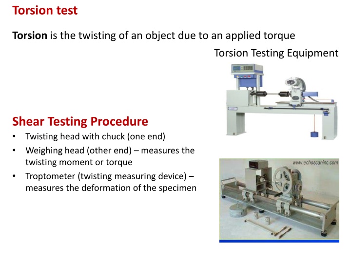
Torsion test Torsion is the twisting of an object due to an applied torque Torsion Testing Equipment Shear Testing Procedure Twisting head with chuck (one end) Weighing head (other end) measures the twisting moment or torque Troptometer (twisting measuring device) measures the deformation of the specimen
Torsion test Ratio of shear stress to the shear strain in the elastic range is called shear modulus, or modulus of rigidity, G G is a quantity related to the modulus of elasticity E Considering a cylindrical bar with one end being twisted as shown in figure 1, the twisting moment MT is resisted by the shear stress existing across the specimen section. This shear stress is zero at the center of the bar, increases linearly with its radius and finally reaches its maximum value at the peripheral of the bar. If the cylindrical bar with a length of L, the twisting moment can be related to the shear stress as follow The shear strain, , can be calculated from equation: Figure1 : Torsion of a solid bar
T = torsional moment, Nm J is the polar moment of inertia, mm4 or in4 G is the shear modulus, N/mm2 or lbf/in2 is degree of rotation, radian r is the radius of the cylindrical bar, mm or in L is the length of the cylindrical bar, mm or in is the shear stress, N/mm2 or lbf/in2 Within the elastic range of deformation, the shear stress can be calculated according to equation: For a solid cylindrical specimen, the polar moment J = D4/32, we can therefore determine the shear stress as shown in equation:
Types of torsion failures It can be seen that the maximum shear stresses exist along two planes, which are perpendicular to each perpendicular to the longitudinal axis (yy) and another is aligned parallel to the longitudinal axis (xx). The principle stresses 1 and 3 are inclined at 45o to the longitudinal axis and have their magnitudes equal to those of the shear stresses. The principle stress 1 is tensile while the principle stress 3 is compressive. The intermediate stress 2 is zero under torsion. other. One is Figure 2: Types of failure in torsion There are two types of torsion failures: 1) Shear (ductile) failure due to the shear stresses affected by the tensile stresses 2) Tensile (brittle) failure due to the tensile stresses affected by the shear stresses