Understanding Resonant Circuits in Electronics Lab
Explore the practical aspects of resonant circuits in an electronics lab, from measuring RMS voltages to estimating angles using simple geometry. Find impedance, analyze with added capacitance, and get ready for resonant circuits in the next session.

Download Presentation

Please find below an Image/Link to download the presentation.
The content on the website is provided AS IS for your information and personal use only. It may not be sold, licensed, or shared on other websites without obtaining consent from the author. If you encounter any issues during the download, it is possible that the publisher has removed the file from their server.
You are allowed to download the files provided on this website for personal or commercial use, subject to the condition that they are used lawfully. All files are the property of their respective owners.
The content on the website is provided AS IS for your information and personal use only. It may not be sold, licensed, or shared on other websites without obtaining consent from the author.
E N D
Presentation Transcript
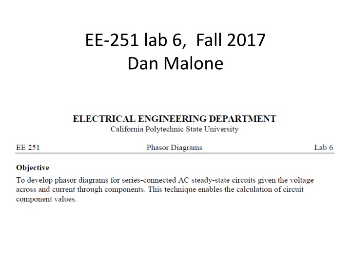
EE-251 lab 6, Fall 2017 Dan Malone
Measure the rms voltages, VR and VZ Then plot them on a phase plane.
Then estimate the angle with a protractor or calculate using VRL and VL or VZ, It s simple high school geometry.
Find the impedance: |ZL| = |VL|/|I| same ZL = RL + jXL Solve using geometry RL = ZL Cos( ) Magnitude only XL = ZL Sin( ) Magnitude only = arctan VL/VRL


")