Understanding Microwave and Radar Engineering
Microwave and radar engineering involve the study of electromagnetic radiation with wavelengths ranging from one meter to one millimeter and frequencies between 300 MHz and 300 GHz. This form of technology plays a crucial role in communication systems due to its advantages such as large bandwidth, better directivity, and the ability to use small-sized antennas.
Download Presentation

Please find below an Image/Link to download the presentation.
The content on the website is provided AS IS for your information and personal use only. It may not be sold, licensed, or shared on other websites without obtaining consent from the author. Download presentation by click this link. If you encounter any issues during the download, it is possible that the publisher has removed the file from their server.
E N D
Presentation Transcript
MICROWAVE & RADAR ENGINEERING
Introduction Microwaves are with wavelengths ranging from about one meter to one millimeter; with frequencies between 300 MHz (1 m) and 300 GHz (1 mm). a form of electromagnetic radiation A more common definition in radio engineering is the range between 1 and 100 GHz (wavelengthsbetween 0.3 m and 3 mm). Microwaves include the entire SHF band (3 to 30 GHz, or 10 to 1 cm) at minimum. Frequencies in the microwave range are often referred to by their IEEE radar band designations: L,S, C, X, Ku, K, or KabanD. 2
prefix micro-in microwave is not meant to suggest a wavelength in the micrometerrange. Rather, it indicates that microwaves are "small" (having shorter wavelengths), compared to the radio waves used prior to microwave technology. The boundaries between far microwaves, and ultra-high-frequency radio waves are fairly arbitrary and are used variously between different fields of study. Microwaves travel by line-of-sight; unlike lower frequency radio waves they do not diffract around hills, follow the earth's surface as ground waves, or reflect from the ionosphere. so terrestrial microwave communication links are limited by the visual horizon to about 40 miles infrared, terahertz radiation, 3
MICROWAVE BANDS Microwavefrequency bands Designation Frequency range Wavelength range Lband 1 to 2 GHz 15 cm to 30 cm Sband 2 to 4 GHz 7.5cm to 15 cm Cband 4 to 8 GHz 3.75cm to 7.5 cm X band 8 to 12GHz 25 mm to 37.5 mm 5
Kuband 12 to 18 GHz 16.7mm to 25 mm K band 18 to 26.5 GHz 11.3mm to 16.7 mm Kaband 26.5to40 GHz 5.0 mm to 11.3 mm Qband 33 to 50 GHz 6.0mm to 9.0 mm Uband 40 to 60 GHz 5.0mm to 7.5 mm 6
ADVANTAGES OF MICROWAVES Large Bandwidth: The Bandwidth of Microwaves is larger than the common low frequency radio waves. Thus more information can be transmitted using Microwaves. It is very good advantage, because of this, Microwaves are used for Point to Point Communications. Better Directivity: At Microwave Frequencies, there are better directive properties. This is due to the relation that As Frequency Increases, Wavelength decreases and as Wavelength decreases Directivity Increases and Beam width decreases. So it is easier to design and fabricate high gain antenna in Microwaves 7
Small Size Antenna: Microwaves allows to decrease the size of antenna. The antenna size can be smaller as the size of antenna is inversely proportional to the transmitted frequency. Thus in Microwaves, we have waves of much higher frequencies and hence the higher the frequency, the smallerthe size of antenna. Low Power Consumption: The power required to transmit a high frequency signal is lesser than the power required in transmission of low frequency signals. As Microwaves have high frequency thus requires very less power. Effect Of Fading: The effect of fading is minimized by using Line Of Sight propagation Frequencies. While at low frequency signals, the layers around the earth causes fading of the signal technique at Microwave 8
APPLICATIONS OF MICROWAVES There Applications of Microwaves. The great example of Application of Microwavesis 'Microwave Oven' which we uses in our daily life. are many Industrial, Scientific, Medical and Domestic Following are the other main applicationareas of Microwaves: Communication RemoteSensing Heating MedicalScience 9
Communication: Microwave is used in broadcasting and telecommunication transmissions. As described above, they have shorter wavelengths and allows to use smaller antennas. The cellular networks like GSM, also uses Microwave frequencies of communication. Microwaves are also used for transmitting and receiving a signal from earth to satellite and from satellite to earth. Military or Army also makes use of Microwaves communication system. They uses X or Ku band communication. range 1.8 to 1.9 GHz for in t h e i r for their 10
Remote Sensing: Most of you may be familiar with this Application. The most common application of Microwave is its use in RADAR and SONAR. RADAR is used to illuminate an object by using a transmitter and receiver to detect its position and velocity. Radiometry is also one of the RemoteSensing Applications. Heating: You all are familiar with this application. We uses Microwave Oven to bake and cook food. It is very convenient electronic machine which performs the heating task very cleanly and in a very less time. If you Want to know How Does a Microwave Works? then you may wonder that is based on the vibration of electrons present in the Food Particles. That is why Microwave Oven heats the food uniformly without heating the container. 11
Medical Science: Microwave's heating properties are also used in Medical Science. Microwave also have Medical Applications such as it is used in diagnosis and various therapies. There are also some other applications of heating as Drying, Precooking and Moisture Leveling. property of microwave such 12
WAVEGUIDES A hollow metallic tube of the uniform cross section for transmitting electromagnetic waves by successive reflections from the inner walls of the tube is called as a Waveguide. Microwaves propagate through microwave circuits, components and devices, which act as a part of Microwave transmission lines, broadly called as Waveguides. A waveguide is generally preferred in microwave communications. A waveguide is a special form of a transmission line, which is a hollow metal tube. Unlike the transmission line, the waveguide has no center conductor. 13
ADVANTAGES OF WAVEGUIDES Waveguidesare easy to manufacture. They can handle very large power (in kilowatts) Power loss is very negligible in waveguides They offer very low loss ( low value of alpha-attenuation) The microwave energy when travels through the waveguide, experienceslower losses than a coaxial cable. 14
Types of waveguides There are five types of waveguides. They are: Rectangularwaveguide Circularwaveguide Ellipticalwaveguide Singleridged waveguide Doubleridged waveguide 15
TransmissionLines Waveguides SupportsTEM wave Cannotsupport TEM wave Only the frequencies that are greater than cut-off frequency can pass through Allfrequenciescan pass through One conductor transmission Twoconductor transmission Wave travels through reflections from the wallsof waveguide Reflectionsare less It has characteristicimpedance It has wave impedance 17
Propagation of waves is accordingto "Circuittheory" Propagation of waves is accordingto"Field theory" Returnconductor is not required as the body of the waveguide acts as earth It has a return conductor to earth Bandwidth is not limited Bandwidthis limited Waves do not disperse Waves getdispersed 18
Rectangular Waveguides Rectangular waveguides are the one of the earliest type of the transmissionlines. They are used in many applications. A lot of components such as isolators, detectors, attenuators, couplers and slotted lines are available for various standard waveguide bands between 1 GHz to above 220 GHz. A rectangular waveguide supports TM and TE modes but not TEM waves because we cannot define a unique voltage since there is only one conductor in a rectangularwaveguide. The shape of a rectangular waveguide is as shown below. A material with permittivity e and permeability m fills the inside of the conductor. 19
A rectangular waveguide cannot propagate below some certain frequency. This frequency is called the cut-off frequency. Here, we will discuss TM mode rectangular waveguides and TE mode rectangular waveguides separately. 20
Modes of wave guides Waveguide modes Looking at waveguide theory it is possible it calculate there are a number of formats in which an electromagnetic wave can propagate within the waveguide. These different types of waves correspond to the different elements within an electromagneticwave. TE mode: This waveguide mode is dependent upon the transverse electric waves, also sometimes called H waves, characterized by the fact that the electric vector (E) being always perpendicular to the direction of propagation. In TE wave only the E field is purely transverse to the direction of propagation and the magnetic field is not purely transverse i.e.Ez=0,Hz#0 21
TM mode: Transverse magnetic waves, also called E waves are characterised by the fact that the magnetic vector (H vector) is always perpendicular to the direction of propagation. In TE wave only the H field is purely transverse to the direction of propagationand the Electric field is not purely transverse i.e.Ez#0,Hz=0 TEM mode: The Transverse electromagnetic wave cannot be propagated within a waveguide, but is included for completeness. It is the mode that is commonly used within coaxial and open wire feeders. The TEM wave is characterised by the fact that both the electric vector (E vector) and the magnetic vector (H vector) are perpendicular to the direction of propagation. In this neither electric nor magnetic fields are purely transverse to the direction of propagation.i.e. Ez#0, Hz#0 22
Modes The electromagnetic wave inside a waveguide can have an infinite number of patternswhich are called modes. The electric field cannot have a component parallel to the surface i.e. the electric field must always be perpendicular to the surface at the conductor. The magnetic field on the other hand always parallel to the surface of the conductor and cannot have a component perpendicular to it at the surface. 23
We have seen that in a parallel plate waveguide, a TEM mode for which both the electric perpendicular to the direction of propagation, exists. This, however is not true of rectangular wave guide, or for that matter for any hollow conductor wave guide without an inner conductor.We know that lines of H are closed loops. Since there is no z component of the magnetic field, such loops must lie in the x-y plane. However, a loop in the x-y plane, according to Ampere slaw,implies an axial current. If there is no inner conductor, there cannot be a real current. The only other possibility then is a displacementcurrent. and magnetic fields are 24
However, an axial displacement current requires an axial component of the electric field, which is zero for the TEM mode. Thus TEM mode cannot exist in a hollow conductor. (for the parallel plate waveguides, this restriction does not apply as the field lines close at infinity.) 25
Guided Wavelength (g) Guided Wavelength ( g): It is defined as the distance travelled by the wave in order to undergo a phase shift of 2 radians. It is related to phase constant by the relation g=2 / the wavelength in the waveguide is different fromthe wavelengthin free space. Guide wavelength is related to free space wavelength 0 and cut-off wavelength c by 1/ g2=1/ 02-1/ c2 The above equation is true for any mode in a waveguideof any cross section 26
Phase Velocity(vp) Phase Velocity(vp): Wave propagates in the waveguide when guide wavelength gis grater than the free space wavelength 0. In a waveguide, vp= gf where vp is the phase velocity. But the speed of light is equal to product of 0and f. This vp is greater then the speed of light since g> 0. The wavelength in the guide is the length of the cycle and vp represents the velocityof the phase. It is defined as the rate at which the wave changes its phase in terms of the guide wavelength. Vp= / Vp=c/[1-( 0/ c)2]1/2 27
Degenerate Modes Degenerate Modes Two or more modes having the same cut-off frequency are called Degenerate modes For a rectangularwaveguide TEmn/TMmnmodes for which both m#0,n#0 will always be degenerate modes. 28
Matched load: Matched Load is a device used to terminate a transmission line or waveguide so that all the energy from the signal source will be absorbed. 29
CIRCUALTORS AND ISOLATORS Both microwave circulators and isolators are non reciprocal transmission devices that use the property of Faraday rotation in the ferrite material. A non reciprocal phase shifter consists of thin slab of ferrite placed in a rectangular waveguide at a point where the dc magnetic field of the incident wave mode is circularly polarized. When a piece of ferrite is affected by a dc magnetic field the ferrite exhibits Faraday rotation. It does so because the ferrite is nonlinear material and its permeability is an asymmetric tensor. 30
MICROWAVECIRCULATORS A microwave circulator is a multiport waveguide junction in which the wave can flow only from the nth port to the (n + I)th port in one direction Although there is no restriction on the number of ports, the four-port microwave circulator is the most common. One type of four-port microwave circulator is a combination of two 3-dB side hole directional couplers and a rectangularwaveguide with two non reciprocal phase shifters. 31
ISOLATOR An isolator is a nonreciprocal transmission device that is used to isolate one component from reflections of other components in the transmission line. An ideal isolator completely absorbs the power for propagation in one direction and provides lossless transmission in the opposite direction. Thus the isolator is usually called uniline. 33
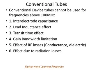
Introduction Limitations of conventional tubes at microwave frequencies: Conventional vacuum tube like triodes, tetrodes and pentodes are less useful signal source at the frequency above the 300 MHz. To see whether or not a conventional device works satisfactory at high frequencies or microwave frequencies, we consider a simple oscillator having LC tuned circuit and try to increase the operating frequency. For this purpose we reduce the tank circuit parameter, either L or C (since =d/v0). For high frequency or microwave frequency the device parameters like the inter electrode capacitance and lead inductance takes the dominant part in the circuit and affect the operation of the oscillator. 35
Introduction There are following reasons for that conventional tube cannot be used for microwave frequency or high frequency. 1. Inter electrode capacitanceand lead inductanceeffect. 2. Transit time effect. 3. Gain-Bandwidth product limitation. 4. RFlosses. 5. Radiationlosses. 36
1.Inter electrode Capacitance and Lead Inductance Effect: The inter electrode capacitances and lead inductances are the order of 1 to 2 pF and 15 to 20 mH respectively. The shunt impedances due to inter electrode becomes very low and series impedances due to lead inductance become very high at the microwave or high frequency which makes these tube unstable. Refinements have been done in the design and fabrication of these tubes with the result that these tubes, like disk seal tube, are still used up to the lower end of microwave spectrum. 2.Transit Time Effect: In a conventional tube electrons emitted by the cathode take a finite (non-zero) time in reaching the anode. This interval, called the transit time, depends on the cathode anode spacing and the static voltage between the anode and the. Transit time ( ) = where is the transit time, d is the cathode anode spacing and is the velocity of electrons. 37
3. Gain-Bandwidth Product Limitation: In ordinary vacuum tubes the maximum gain is generally achieved by resonating the output tunes circuit. Gain-bandwidth product = Amax BW = (gm/ G) (G/C) Where gm is the transconductance, Amax BW= gm/ C . It is important to note that the gain-bandwidth product is independent of frequency. As gm and C are fixed for a particular tube or circuit, higher gain can be achieved only at the applicable to resonant circuit only. 38
In microwave device either re-entrant cavities or slow- wave structures are used to obtain a possible overall high gain over a broad bandwidth. 4. RF Losses: RF losses include the skin effect losses and dielectric losses. (a) Skin effect losses: Due to skin effect, the conductor losses came into play at higher frequencies, at which the current has the tendency to confined itself to a smaller cross-section of the conductor towards its outer surface. 39
(b)Dielectric losses: At the microwave frequency or high frequency various insulating materials like glass envelope, silicon and plastic encapsulations are used. The losses occur due to dielectric materials is known as dielectric loss generally the relationship between the power loss in dielectric and frequency is given by PL ? f So, if frequency increases then power loss will also increases. The effect of dielectric loss can reduced eliminating the tube base and reducing the surface area of the dielectricmaterial. 5. Radiation Losses: At high frequency, when the dimensions of wire approaches near to the wavelength ( = c/f). It will emit radiation called radiation losses. Radiation losses are increases with the increase in frequency. Radiation loss can be reduced by proper shielding of the tube and its circuitry. 40
Klystron Klystron is the simplest vacuum tube that can be used for amplification or generation (as an oscillator) of microwave signal. The operation of klystron depends upon velocity modulation which leads to density modulation of electrons. Klystron may be classified as gives below: 1. Two cavity klystron amplifier 2. Multi cavity klystron3. Reflex klystron. 41
TWO CAVITY KLYSTRON AMPLIFIER One of the earlier form of velocity modulation device is the two cavity klystron amplifier, represented by the schematic of figure. It is seen that high velocity electron beam is formed, focused and sent down along a glass tube to a collector electrode, which is at a high positive potential with respect to the cathode. As it is clear from the figure, a two cavity klystron amplifier consists of a cathode, focussing electrodes, two buncher grids separated by a very small distance forming a gap A (Input cavity or buncher cavity), two catcher grids with a small gap B (output or catcher cavity)followed by a collector. 42
Figure 43
Operation The input and output are taken from the tube is via resonant cavity with the help of coupling loops. The region between buncher cavity and catcher cavity is called drift space. The first electrode (focussing grid) controls the number of electrons in the electron beam and serves to focus the beam. The velocity of electrons in the beam is determined by the beam accelerating potential. On leaving the region of focussing grid, the electrons passes through the grids of buncher cavity. The space between the grids is referred to as interaction space. When electrons travel through this space, they are subjected to RF potential at a frequency determined by the cavity resonant frequency which is nothing but the input frequency. 44
Operation The amplitude of this RF potential between the grids is determined by the amplitude of the input signal in case of an amplifier or by the amplitude of feedback signal from the second cavity if used as an oscillator. The working of two cavity klystronamplifier depends upon velocity modulation. 45
Velocity Modulation Consider a situation when there is no voltage across the gap. Electrons passing through gap A are unaffected and continue on to the collector with the same constant velocities they had before approaching the gap A. When RF signal to be amplified is used for exciting the buncher cavity thereby developing an alternating voltage of signal frequency across the gap A. The theory of velocity modulation can be explain by using the diagram known as Applegate diagram as shown in figure. At point X on the input RF cycle, the alternating voltage is zero and electron which passes through gap A is unaffected by the RF signal 46
Let this electron is called reference electron eR which travels with an unchanged velocity , to cathode voltage. Consider another point Y of the RF cycle an electron passing the gap slightly later than the reference electron eR, called the late electron eL is subjected to positive RF voltage so late electron eL is accelerated and hence travelling towards gap B with an increased velocity and this late electron eL tries to catch the reference electron eR. Similarly, another point Z of RF cycle, an electron passing the gap slightly before than the reference electron eR, called the early electron ee and this early electron is subjected to negative RF voltage so early electron ee is retarded and hence travelling towards gap B with reduced velocity and reference electroneR catches up the early electronee. where V is the anode 47
So, when the electron pass through the buncher gap their velocity will be change according to the input RF signal.This process is known as velocity modulation. 48
Applegate diagram, the electrons gradually bunch together as they travel in the drift space. When an electron catches up with another one, the electron will exchange energy with the slower electron, giving it some excess energy and they bunch together and move on with the average velocity of the beam. This phenomena is very vital to the operation of klystron tube as an amplifier. The pulsating stream of electrons passes through gap B and excited oscillation in the output cavity. The density of electron passing the gap B varies cyclically with time. This mean the electron beam contains an AC current and variation in current density (often called current modulation) enables the klystron to have a significant gain and hence drift space converts the velocitymodulationinto current modulation. 49


