Understanding Logic Design and Hardware Control Language
Exploring the fundamental concepts of logic gates, combinatorial circuits, HCL, TAPPS, multiplexors, and the differences between HCL and C language regarding Boolean expressions and circuit evaluation. Learn how HCL handles word-level signals and constructs word-level circuits.
- Logic Design
- Hardware Control Language
- Combinatorial Circuits
- Boolean Expressions
- Word-level Circuits
Download Presentation

Please find below an Image/Link to download the presentation.
The content on the website is provided AS IS for your information and personal use only. It may not be sold, licensed, or shared on other websites without obtaining consent from the author. Download presentation by click this link. If you encounter any issues during the download, it is possible that the publisher has removed the file from their server.
E N D
Presentation Transcript
Logic Design and Hardware Control Language Paul Bodily
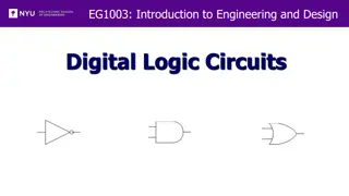
Logic gates the basic computing elements for digital circuits logic gates are always active they are linked together in combinatorial circuits to achieve more complex operations HCL We use hardware control language (HCL) to describe control logic of processor designs
Combinatorial circuits restrictions Logic gate inputs can come from 1. a system or primary input 2. memory 3. output of a logic gate Outputs of 2 logic gates can't be connected together Must be acyclic bool eq = (a && b) || (!a && !b); HCL
TAPPS In general, the signals eq and xor will be complements of each other. That is, one will equal 1 whenever the other is 0.
Multiplexor ("MUX") selects a value from among a set of different data signals out will equal a when s is 1 b when s is 0
HCL vs C bool eq = (a && b) || (!a && !b); HCL C combinatorial circuits are always on boolean expressions are evaluated when encountered in a C program can operate on arbitrary integers (0 = false, everything else is true) only operates on 0 and 1 no evaluation rules might only be partially evaluated e.g., (a && !a) && func(b,c) if first expr is false, doesn't evaluate second
From bits to words HCL In HCL, we will declare any word-level signal as an int, without specifying the word size
Word-level circuits In HCL, we will declare any word-level signal as an int, without specifying the word size medium-thickness lines = set of wires carrying the individual bits of the word dashed line = single-bit signal
Word-level MUX Signetics S54S157 quad 2:1 mux out will equal input word A when the control signal s is 1, and it will equal B otherwise Rather than replicating the bit- level multiplexor 64 times, the word-level version reduces the number of inverters by generating !s once and reusing it at each bit position HCL
MUX in HCL Multiplexing functions are described in HCL using case expressions Like switch statements, but cases in HCL don't have to be mutually exclusive (in hardware, they do some conversion required there) selection expressions are evaluated in sequence, and the case for the first one yielding 1 is selected Common that final case is 1 (default)
Four-way MUX HCL # comment
TAPPS ?
TAPPS ? ? ? ? ?
Arithmetic/Logic Unit (ALU) Combinational logic circuits can get complex (beyond our scope) One last important example: ALU depending on the setting of the function input, the circuit will perform one of four different arithmetic and logical operations Four cases correspond to 4 OPlY86-64 instructions
Function Code addl 6 0 Set Membership subl 6 1 andl 6 2 Consider the scenario in which We are using a MUX to represent an instruction The input signals determine which operation is actually performed We want to set the input signals s1 and s0 based off of some function code In general, when testing whether some code matches one of several possibilities, could write it like this: xorl 6 3 Set membership notation provides more concise format:


