Understanding Inductance in Electrical Engineering
Explore the concept of inductance in electrical circuits through illustrations and explanations of magnetic flux, right-hand rules, solenoids, and toroidal inductors. Learn how inductance is defined, calculated, and applied in practical scenarios.

Download Presentation

Please find below an Image/Link to download the presentation.
The content on the website is provided AS IS for your information and personal use only. It may not be sold, licensed, or shared on other websites without obtaining consent from the author. If you encounter any issues during the download, it is possible that the publisher has removed the file from their server.
You are allowed to download the files provided on this website for personal or commercial use, subject to the condition that they are used lawfully. All files are the property of their respective owners.
The content on the website is provided AS IS for your information and personal use only. It may not be sold, licensed, or shared on other websites without obtaining consent from the author.
E N D
Presentation Transcript
ECE 3318 Applied Electricity and Magnetism Spring 2024 Prof. David R. Jackson Dept. of ECE Notes 31 Inductance 1
Inductance Consider a single loop carrying a current: Right-hand rule for determining the direction of the magnetic field from a current. S I Note that the current shown here (flowing counterclockwise) produces a magnetic flux that goes up through the loop. Single turn coil The current I produces a flux though the loop. 2
Inductance Magnetic flux through loop: B ndS Wb n S n = unit normal to loop S The unit normal is chosen from a right hand rule for the inductor flux . I Right-hand rule: The fingers are in the direction of the current reference direction, and the thumb then gives the direction of the unit normal for the flux calculation. Single turn coil (In this picture, is the flux going up.) H L Definition of inductance: Note:Lis always positive I 3
Right-Hand Rules Note: Please see the Appendix for a summary of right-hand rules. 1) RH rule for Stokes s theorem 2) RH rule for Faraday s law 3) RH rule for Ampere s law 4) RH rule for the direction of the magnetic field 5) RH rule for the inductor flux 4
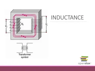
N-Turn Solenoid I N = total flux We assume here that the same flux cuts though each of the N turns. = N = flux through one turn N = L The definition of inductance is now I I 5
Example Note: FindL We neglect fringing here and assume that we have the same magnetic field in the core as if the solenoid were infinite. = L N sL I a r z ( ( ( ( ) ) ) ) = B n 2 a I N turns = 2 a B = / z n N L s = 2 a H 0 r z = z : n RH rule for inductor flux ( ) = 2 a nI 0 r so From previous notes: ( ) ( ) ( ) = = = z nI , H a 2 / L N a nI I 0 r 0, a = / n N L Note : s 6
Example (cont.) sL a r z I N turns Final result: 2 N L ( ) H = 2 L a 0 r s Note:L is increased by using a high-permeability core! 7
Example Toroidal Inductor N turns I R r Find H inside toroid Note: This is a practical structure, in which we do not have to neglect fringing and assume that the core length is very large in order for the answer to be accurate. Find L 9
Example (cont.) N turns I R r The radius R is the average radius (measured to the center of the toroid). r Assume a A = H H = 2 Ais the cross-sectional area: A a 10
Example (cont.) H dr = I encl C I ( ) = H d I encl C r so r C 2 = H d I encl N turns Hence 0 I ( ) = 2 = H I encl H encl 2 We then have RH rule in Ampere's law : NI = A/m [ ] H = + I NI 2 encl 11
Example (cont.) RH rule for the inductor flux = + : N = L n I = 2 A a a N I N turns ( ) B n A L I ) ( N I B A = R R ) ( r N I N I = H A 0 r = R NI = A/m [ ] NI H = A 2 0 r 2 R Hence 2 N = [H] L A 0 r 2 R 12
Example Coaxial cable Ignore flux inside wire and shield (PEC conductors) I Find Ll a I (inductance per unit length) h z b A short is added at the end to form a closed loop. I I z Center conductor - S + h Note: We calculate the flux through the surface Sshaded in green. 13
Example (cont.) = + n RH rule for the inductor flux : I I z Center conductor - n S + h = B ndS = = B dS H dS = L I S S S 14
Example (cont.) I I z Center conductor - n S + h = a = = b I H dS = H (derived previously for the coax) 2 S b b I I b = h H d = = ln h d h a 2 2 a a 15
Example (cont.) I I b = ln h 2 a a I I b a = h ln h z 2 b 1ln 2 b a = = L h Hence I b a = ln H/m [ ] 0 L r Per-unit-length: l 2 16
Example (cont.) Recall: L C = l Z 0 l b a = ln H/m [ ] 0 L r l 2 Note: r = 1 for most practical coaxial cables. From previous notes: 2 = [F ] 0 b a r l C /m ln Hence: b a = = 376.7603 [ ] 0 = 0 [ ] ln 0 Z r 0 0 2 (intrinsic impedance of free space) r 17
Voltage Law for Inductor y C Apply Faraday s law: B x d dt E dr = = = n z C ( ) z = B ndS B A S - + ( ) v t Reminder: In Faraday s law, the unit normal is chosen from the right-hand rule, according to the direction of the path C. Here, = - z. PEC wire: Hence B ( ) d = E dr = E dr v t ( ) = v t z dt A C Note: There is no electric field inside the wire. Here is the flux coming out of the page. 18
Voltage Law for Inductor (cont.) y B d x ( ) = v t z dt From the inductor definition we have: so ( ) d Li dt - + = + Li ( ) ( ) = v t v t z or Note: di ( ) The direction of the current is chosen from the right-hand rule for the inductor flux. = v t Ldt Note:We are using the passive sign convention here. 19
Voltage Law for Inductor (cont.) Summary of Inductor Law di ( ) = v t Ldt - + ( ) v t Note:We are using the passive sign convention here. 20
Energy Stored in Inductor di ( ) = v t Ldt L di dt ( ) = = p t vi L i t t di dt ( ) ( ) L i = = W t p t dt dt + v - i 0 0 t = 0 ( ) i t ( ) i t 1 2 1 2 +- ( ) v t = = = 2 2 L idi L i Li ( ) 0 = 0 i ( ) 0 ( ) 0 i i Hence. we have: For DC we have: 1 2 1 2 ( ) t ( ) t J = 2 = 2 J U Li U LI H H 21
Energy Formula for Inductor We can write the inductance in terms of stored energy as: 2 U I = L H 2 1 2 = B H dV U Next, we use H V 1 I = B H dV L We then have 2 V This gives us an alternative way to calculate inductance. 22
Example Find L using the energy formula N a z Solenoid sL 2 1 2 N L = 2 2 U a I From a previous example, we have 0 H r s 2 U I = Energy formula: L H 2 2 N L H = 2 L a Hence, we have 0 r s 23
Example Find Llusing the energy formula 1 I = B H dV L 2 V I 1 I 2 = L H dV 0 r 2 a V I 1 I = 2 H dV 0 r 2 h b V z 2 2 h b 1 I I = d d dz 0 r 2 2 Coaxial cable 0 0 a 2 b 1 1 ( )( h ) = 2 d Note: 0 r 2 We ignore the magnetic stored energy from fields inside the good conductors. (We would have fields inside the conductors at DC, but not at high frequency.) a 24
Example (cont.) 2 b 1 1 ( )( h ) = 2 L d I 0 r 2 a h b a a I = ln 0 2 r h b z b a = ln L 0 r H/m Per-unit-length: l 2 Note: We could include the stored energy inside inner wire region and the shield region if we were at DC. These contributions would give us the internal inductance of the coax. This would only be important at low frequency, not high frequency, for good conductors. 25
Internal Inductance Internal inductance per unit length of straight infinite wire This comes from the energy stored inside the conductor. z Take one-meter length in z direction: 1 2 r wire = B H dV int H U V 2a 2 a 1 2 ( ) 1 = d d wire r 2 H 0 1 m DC current 0 0 Ampere s law: (Use counterclockwise Amperian path.) 2 I I I ( ) = = = encl H a 2 2 2 2 2 a a wire r = int [H/m] 0 lL 2 Final result: = : a I I 8 encl 2 a 26
Example sL External inductance: a 2 N L ( ) r H z = ext 2 L a 0 r s I N turns (from previous calculation) Internal inductance: wire r wire r H = int 2 0 L aN = int [H/m] 0 lL 8 8 (from wire formula) 27
Appendix In this appendix we summarize the various right-hand rules that we have seen so far in electromagnetics. 28
Summary of Right-Hand Rules ( ) Fingers are in the direction of the path C, the thumb gives the direction of the unit normal. V dr = V n dS Stokes s theorem: C S d dt B E dr = Fingers are in the direction of the path C, the thumb gives the direction of the unit normal for calculating the flux. Faraday s law: (stationary path) C = n dS S Fingers are in the direction of the path C, the thumb gives the reference direction for the current enclosed. H dr = I Ampere s law: encl C = n I J dS encl S 29
Summary of Right-Hand Rules (cont.) Magnetic field law: For a wire or a current sheet or a solenoid, the thumb is in the direction of the current and the fingers give the direction of the magnetic field. (For a current sheet or solenoid, the fingers are simply giving the overall sense of the magnetic field direction.) Inductor flux rule: L I Fingers are in the direction of the current I and the thumb gives the direction of the unit normal for defining the flux. = n B dS S 30


")


")
")
")

")
")
")
")

")
")


")


")