Understanding Fuel Spray & Wall Interactions in MPFI Systems for Green Vehicle Development
Explore the significance of fuel spray and wall interactions in port fuel injection systems through in-depth analysis. Learn about the anatomy of modern injectors, types of fuel jet breakup, and field acceptability testing methods. Gain insights into Yamaha Motor's technical review and proposed solutions with detailed geometrical and technical aspects.
Download Presentation

Please find below an Image/Link to download the presentation.
The content on the website is provided AS IS for your information and personal use only. It may not be sold, licensed, or shared on other websites without obtaining consent from the author. Download presentation by click this link. If you encounter any issues during the download, it is possible that the publisher has removed the file from their server.
E N D
Presentation Transcript
Fuel Spray and Wall Interactions in Ports of MPFI System P M V Subbarao Professor Mechanical Engineering Department Post Spray Process are more Crucial for Post Spray Process are more Crucial for Development of Green Vehicles Development of Green Vehicles
Anatomy of Modern Injectors to generate Pulsating Fuel Flow Jets Solenoid Magnet
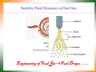
Types of Fuel Jet Breakup What exactly going to Happen in Level 1: Jet Breakup in Quiescent Ambience MPFI System ??? Level 3: Jet Breakup in a pipe flow Level 2: Jet Breakup in an air flow Level 4: Jet Breakup due to wall interactions
YAMAHA MOTOR TECHNICAL REVIEW Shoichi Kato, Takanori Hayashida, Minoru Iida MEP 380 kPa, A/F : 14.5, Coolant Temp. 80
Method of Field Acceptability Testing Select a range and resolution of Start of Injection. This is measured as degrees before compression top dead center (BCTDC). For each value of selected SIT, collect 600 samples of instantaneous p- diagrams. Compute IMEP for each p- diagram. For a given SIT, you have 600 random values of IMEP. Calculate mean and SD for these IMEP values. Define Coefficient of Variation (CoV) as: = 100 COV Least value of CoV signifies most reliable operation and design.
Selection of Injection Timing & Durations All Systems
Air Fuel Interactions in the Manifold As the droplet group enters in the air stream, it decelerates or accelerates depending on local flow geometry. At the same time, the vaporization of droplets is initiated. As the droplets move to the end of the port, some of the unvaporized droplets are expected to impinge on the intake port wall bend to form droplet deposition films. Because of the heat transfer from the wall and from the air stream, these liquid films also continuously generate fuel vapours.
Spray Wall Impingement & Formation of Films The shape, size and location of impingement sites depend on; Fuel spray cone angle. Injection timing, back flow Injection distance, Impingement incidence angle. For every impingement site, there exist; the impingement probability and the passing-by probability. The impingement probability is proportional to spray covered wall area and the downstream flow cross-sectional area.
Maxwells Theory of Particle Surface Interactions A particle impacting on a solid surface first undergoes an elastic deformation and rebound.
Kinematics of Liquid Droplet Impingement It is very different from Maxwell s theory. A droplet impacting on a solid surface first undergoes deformation and spreads out at a certain velocity under the impingement- induced pressure gradients. This spreading flow either remains stable or becomes unstable, leading to different impingement regimes:
Physics of Liquid Droplet Impingement on A Wall The wall impingement process is classified as four regimes: The regime transition criteria are determined based on the Reynolds number and Weber number of the incident droplet and the surface condition: drop drop l drop We drop V D 2 V D l drop = Re = drop l l Re 10 We We H drop drop drop cr 5 We 5 10 We drop & Re We H drop drop drop cr splash is the most important and also the most complex. Spread and Splash are commonly observed in SI engine ports.
Characterization of Liquid Droplet Impingement Two basic issues arise in liquid droplet impingement processes. Occurrence of type of Impacting regime. Post-impingement characteristics, namely, the rebound velocity magnitude and its direction for the rebound regime, the fraction of the mass deposited on the wall and the size and velocity distributions of the secondary droplets for the splash/breakup regime.
Spreading Dynamics of Films There are two different forces exerted on a fuel wall film. On the gas side, the gas flow tends to drive the film moving along the same direction. On the wall side, the viscous friction tends to resist the film movement. The force balance on the film gives the equation for the film motion: V d = film dt impact film drag friction ( V ) 1 = C V V V drag f air air port fs air port fs 2 m U V film d f SMF t impact = = 2 friction fuel A t film
The Splash Splash results in the rebounding of many smaller secondary droplets from the impinging location. The size and velocities of the secondary droplets are statistically distributed. : non-dimensional surface roughness = (roughness height/incident droplet diameter), : non-dimensional film thickness =(film thickness/incident droplet diameter) The splash threshold film thickness Hcr 1 650 . 0 ( ) = + 1 . 0 + 5 . 0 , 5 . 0 drop 1500 Re min H cr 42
Deposited Film Mass Fraction * h The ratio of the reflected to the impinging mass is given by 98 . 3 m impinge Ohnesorge numbers m ref = 21Re 11 SMD 51 . . 9 21 10 Oh = Oh D SMD
