Understanding Electronic Sensors: Basics and Applications
Explore the fundamentals of electronic sensors, including voltage divider rule, potentiometers, operational amplifiers, comparators, and temperature sensors. Learn how sensors quantify physical properties and translate them into signals for interpretation.

Download Presentation

Please find below an Image/Link to download the presentation.
The content on the website is provided AS IS for your information and personal use only. It may not be sold, licensed, or shared on other websites without obtaining consent from the author. If you encounter any issues during the download, it is possible that the publisher has removed the file from their server.
You are allowed to download the files provided on this website for personal or commercial use, subject to the condition that they are used lawfully. All files are the property of their respective owners.
The content on the website is provided AS IS for your information and personal use only. It may not be sold, licensed, or shared on other websites without obtaining consent from the author.
E N D
Presentation Transcript
Preliminaries: The voltage divider rule Comes from applying KVL and KCL For Resistors R1and R2: ???? ???= ?1+?2 ?2 R1 ?? Vin + R2 ?2 Vout - ????= ?1+?2???
Preliminaries: The potentiometer Three terminal device Fixed resistance between end terminals Sliding resistance for middle terminal Voutcan be adjusted from 0 to Vin by turning potentiometer knob R1 +R2 = fixed resistance R1 Vin + R2 Vout -
Preliminaries: The Operational Amplifier MCP6002 Operational amplifier (op-amp): two input pins one output pin Two pins for power -or- one power & one ground) A is the open-loop gain and is very large (approaching infinity) Input resistance is large ( Multiple op-amps can come on a single chip that shares power pins - + + + + V-(t) - Vout(t) - V+(t) - Vout(t)=A[V+(t)-V-(t)] )
Preliminaries: The Comparator circuit Op-amp output will always be between the supply voltages VSS vout(t) VDD. Because of the large open-loop game, most op-amp circuits have feedback. A comparator has no feedback, so: Vout= VDDif v+> v- Vout= VSSif v+< v- Use potentiometer on one side to adjust transition level
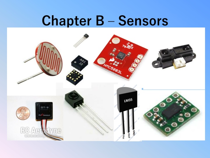
Sensors A sensor is a device that (quantitatively) measures some physical property and maps the observation into a signal which can be understood by an observer. Electronic sensors generate a voltage or current that can be interpreted via circuitry and a calibration table or formula to give the quantitative state of the physical property to within some error or tolerance. The process of calibration and error estimation is critical to successful sensor operation. Most off-the-shelf sensors come with standard calibration data and error estimates
Temperature sensors We will use the TMP 36 Low voltage operation (2.7 V to 5.5 V) 10 mV/ C scale factor Temp ( C) = 100*vout- 50 2 C accuracy over temperature range 0.5 C linearity The TMP 36 is a silicon bandgap sensor that works because the forward voltage of a silicon diode is temperature-dependent. A BJT is often used, and so VBE depends ~linearly on the temperature.
Using the TMP36 with an op-amp VDD - + 3.3V + Vout(t) - VSS One can adjust pot so that Vout = VDD for all temperatures above some threshold and Vout = VSS for all temperatures below that threshold.
CdS Photoresistor A photoresistor is a light-controlled variable resistor. The resistance of a photoresistor decreases with increasing incident light intensity. CdS photoresistors are inexpensive and widely used (but are not RoHS-approved because of the Cadmium). To detect an on/off light situation: 1. Measure the on and off CdS resistances. Typically they are a few k . 2. Chose a fixed resistor whose resistance is about the average of the two CdS resistances. 3. Build a voltage divider with the fixed and photoresistor as in figure 4. Connect the middle connection to a comparator circuit
Using a CdS Photoresistor with an op-amp VCC - + + 3.3V Vout(t) - R VDD One can adjust the potentiometer so that Vout = VCC when light is off and Vout = VDD when light is on. R should be near the average of the photoresistor s on and off resistances.
PIR Sensors Passive (or Pyroelectric) infrared sensors (PIR sensors) are electronic sensors that measure infrared (IR) light radiating from objects in their field of view. They are often used in PIR-based motion detectors. Example specifications: Output: Digital pulse high (3V) when triggered (motion detected) digital low when idle (no motion detected). Pulse lengths are determined by resistors and capacitors on the PCB and differ from sensor to sensor. Sensitivity range: up to 20 feet (6 meters) 110 degrees x 70 degrees detection range Power supply: 3.3V - 5V input voltage,
More on IR sensors Some IR sensors are designed to work in pairs with transmitters. That can be designed to : detect presence (digital output) - TSSP4038 determine relative proximity (analog output) TSOP58P38 pulse width is linearly proportional to distance Both operate at 38 kHz
Distance / proximity sensor Can be: Infrared with Tx/Rx in same package Example: GP2Y0A21YK; Range: 5-80 cm Ultrasonic Example: HC-SR04; Range: 2-450cm 3mm Capacitive (close range) Inductive (close range)
Other sensor types: Touch sensors Mechanical (pushbutton) or capacitive Magnetic sensors Often based on Hall effect 1, 2, or 3-axis models May be digital (switches) or analog Saturation level important Vibration sensors Motion detection
Distance Sensor: GP2Y0A21 IR sensor operating voltage: 4.5 V to 5.5 V average current consumption: 30 mA (typical) distance measuring range: 10 cm to 80 cm (4" to 32") output type: analog voltage output voltage differential over distance range: 1.9 V (typical) response time: 38 10 ms
Distance Sensor: HC-SR04 Ultrasonic sensor Working Voltage: DC 5V Working Current: 15mA Working Frequency: 40 kHz Max Range: 4m Min Range: 2cm Resolution: 0.3 cm Measuring Angle: 15 degree Trigger Input Signal: 10 S TTL pulse
Distance measurement Emit 10 microsecond pulse. Measure delay for return signal. Twice distance is speed of sound x delay Speed of sound So distance (in) = delay (ms) *6.7 = 34 cm /millisecond = 13.4 inches / ms
Magnetic Sensors There are many types of sensors Hall Effect GMR (magneto-resistive)sensors Different number of axes (1-3) Analog or Digital outputs Different ranges of sensitivity, linearity, saturation Directional vs. total With or w/o hysterersis
3-Axis Digital Compass IC HMC5883L Based on Honeywell s GMR HMC118X sensor Supply voltage 2.2 2.6V Field range +/- 8 Gauss Auto Degaussing 12 Bit A/D converter I2C serial communication
ADXL345 3-axis accelerometer I2C or SPI output Programmable from +/- 2 g to +/- 16 g Can store offset values 13 bit resolution (+/- 4096) Senses free-fall Senses lack of motion
Other sensor types: Accelerometers (MEMS) Up to 3-axis detect gravitational effects Range of sensitivities 3G, 9G, etc May have digital or analog outputs Gyros (MEMS) Need to integrate data to get angular position IMU (Inertial Measurement Unit) sensor a measurement unit designed to contain accelerometers and gyros, and sometimes magnetic sensors and altimeters
10 degree-of-freedom IMU Pressure sensor BMP085 MEMS gyroscope L3G4200D Accelerometer ADXL345 (+/- 2g - +/- 16g) Digital Compass HMC5883L
Sample code for light detection // Light_detect.c // // Turns an LED on when the lights go off, and // Turns an LED off when the lights go on // // gcc -o Light_detect Light_detect.c -l bcm2835 // sudo ./Light_detect // #include <bcm2835.h> #include <stdio.h> // LED on RPi Plug P1 pin 12 (which is GPIO pin 18) // Sensor on RPi Plug P1 pin 15 (which is GPIO pin 22) #define LED RPI_GPIO_P1_12 #define Sensor RPI_GPIO_P1_15 //
The light detect program continued int main(int argc, char **argv) { if (!bcm2835_init()) return 1; // Set RPI pin P1-12 to be an output bcm2835_gpio_fsel(LED, BCM2835_GPIO_FSEL_OUTP); // Set RPI pin P1-15 to be an input bcm2835_gpio_fsel(Sensor, BCM2835_GPIO_FSEL_INPT); // pull up the output to one when not connected bcm2835_gpio_set_pud(Sensor, BCM2835_GPIO_PUD_UP); // And a low detect enable
The light detect program continued while (1) { // Read some data uint8_t value = bcm2835_gpio_lev(Sensor); printf("read from pin 15: %d\n", value); if (value) { // Turn on LED bcm2835_gpio_write(LED, HIGH); } else { // turn off LED bcm2835_gpio_write(LED, LOW); } bcm2835_delay(500); } bcm2835_close(); return 0; }