Understanding Electrical Filters: Types, Uses, and Frequency Response
Explore the world of electrical filters through this comprehensive guide covering different types of filters, frequency response graphs, and practical applications. Learn about low-pass, high-pass, and band-pass filters, how they work, and their significance in signal processing. Discover the concept of the -3dB point, cutoff frequencies, and how filters can be utilized in creating circuit elements like crystal set radios. Gain insights into frequency response graphs and how to identify filters based on generated graphs.

Uploaded on Sep 18, 2024 | 0 Views
Download Presentation

Please find below an Image/Link to download the presentation.
The content on the website is provided AS IS for your information and personal use only. It may not be sold, licensed, or shared on other websites without obtaining consent from the author. Download presentation by click this link. If you encounter any issues during the download, it is possible that the publisher has removed the file from their server.
E N D
Presentation Transcript
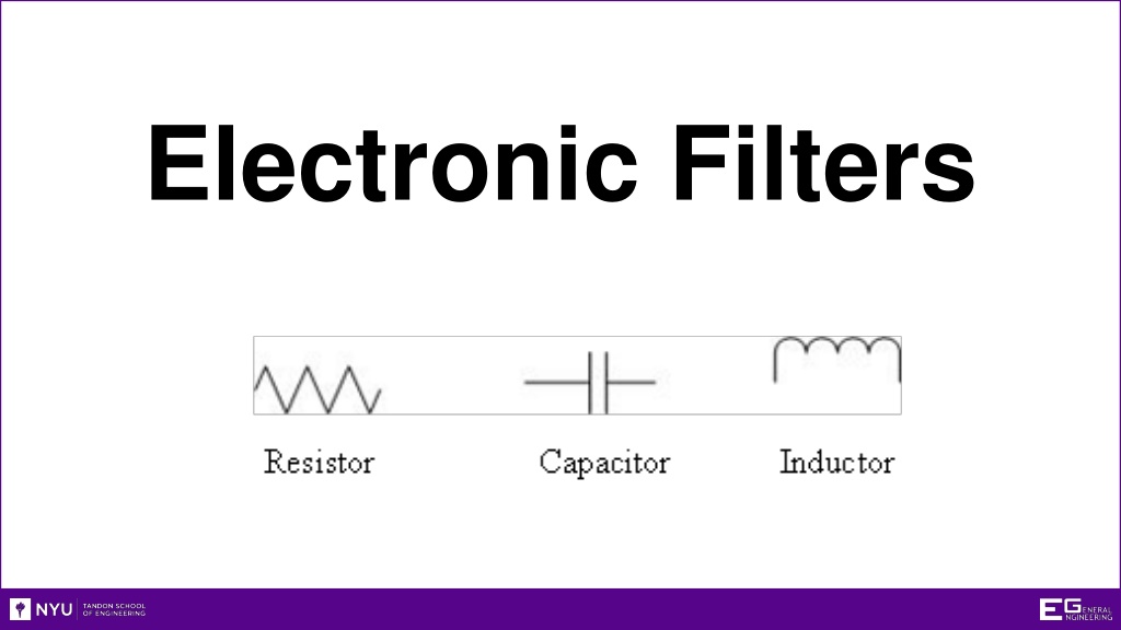
Electronic Filters https://manual.eg.poly.edu/images/6/6f/Lab_filters_4.gif
Overview Objective Background Materials Procedure Report/Presentation Closing
Objective Learn about electrical filters Different types Uses What is the -3dB point? Create filters and a crystal set radio using multiple circuit elements Identify filters based on generated graphs
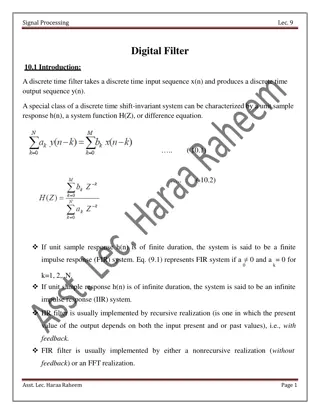
Frequency Response Graph Gain (dB) Ratio of output against input (20)log(???? ???) Always negative value -3dB Point 3dB drop of signal power from highest point on gain Signal power is half of original value Cutoff Frequency (Hz) Frequency at -3dB Point
Frequency Response Graph Plot Gain vs. Frequency Gain vs. Frequency of electrical signal Max Gain (dB) Gain (dB) (linear scale) Gain is 3 dB lower than the max Semi-logarithmic scale 3 dB Linear y-axis, logarithmic Bandwidth Cutoff Frequency f (kHz) (log scale) x-axis
What are Filters? Eliminate unwanted frequencies High-pass or low-pass Favor desired frequencies Band-pass Bandwidth: frequency range filter allows to pass Example: Radio tunes in to particular station
Basic Filter Types Low-Pass Filter Allows low frequencies to pass 3dB Point: -3dB Cutoff Frequency: 1590 Hz Bandwidth: 0-1590 Hz IGNORE PASS
Basic Filter Types High-Pass Filter Allows high frequencies to pass 3dB Point: -3dB Cutoff Frequency: 160 Hz Bandwidth: 160 - Hz IGNORE PASS
Basic Filter Types Band-Pass Filter Allows a limited range of frequencies to pass 3dB Point: -3dB Cutoff Frequency: 400 - 600 Hz Bandwidth: 400 - 600Hz Resonant Frequency (High Response Point): 500 Hz IGNORE IGNORE PASS
Electrical Terminology Voltage (V) Potential difference in electrical energy Units = volts (V) Current (I) Charge flow rate Can be positive or negative Units = amperes (A)
Electrical Elements Resistor (R) Resists flow of electrical current Dissipates electrical energy as heat Often used to alter voltages in circuits Symbol Characterized by Ohm s Law: V = I*R Not sensitive to frequency Uses a poor conductor (ex: carbon) Units = Ohms ( )
Electrical Elements Capacitor (C) Stores potential energy (V) Symbol Affected by voltage and frequency A pair metal plates separated by non- conductive material (ex: air) Electrical charge accumulates on plates Units = Farads (F)
Electrical Elements Inductor (L) Stores and delivers energy in a magnetic field Symbol Magnetic fields affect the current of a circuit Effected by current and frequency Is a coil of wire Units = Henries (H)
Electrical Wiring Series Same current through all elements Vin = VA + VB + VC Parallel Same voltage across all branches Vin = VD = VE = VF + VG
Materials Resistors Brown, black, yellow = 100K Brown, black, green = 1M Capacitors 102 = 0.001 F 10J = 10pF Inductors 1mH
Materials NI-ELVIS II+ Breadboard Coaxial to alligator clip cable
Procedure Testing 1. Plug in NI ELVIS II to PC Lab and turn it on 2. Select NI ELVISmx Instrument Launcher 3. Select FGEN in the Instrument Launcher 4. Set function generator to 1000Hz 5. Set the amplitude to 2 Vpp 6. Set signal route to FGEN BNC 7. Select Scope in the Instrument Launcher
Procedure Data Analysis Click run in both instruments Calculate the -3dB point Test both of the circuits and determine their type Assemble the radio
Procedure Circuit 1 Connect the 100k resistor and .001 F capacitor in series
Procedure Circuit 2 Connect 0.001 F capacitor to 1 M resistor in series
Assignment: Presentation Assemble the circuit below (Crystal Radio)
Assignment: Report Individual Report (one report per student) Title page Discussion topics in the manual For all circuits Include Excel tables and Gain vs. Frequency graphs Determine filter type Label each graph with determined filter type OPTIONAL- Include photos of circuits and setup
Assignment: Report Team Presentation Include lab data Professional-looking tables Discussion topics in the manual Include photos of circuits and setup Refer to Creating PowerPoint Presentations found in Online Manual
Closing TA will assign which circuit you start with Have all original data signed by your TA All team members must actively participate in experiment Submit all work electronically Return all materials to your TA