Understanding diode clipper circuits with DC supply impact
Diode clipper circuits, such as series and parallel configurations with DC supplies, have a significant effect on signal analysis. By defining output voltages, determining transition voltages for diode states, and exploring waveform responses, these circuits can be analyzed effectively to understand their behavior. Practical examples and detailed diagrams aid in grasping the concepts presented.
Download Presentation

Please find below an Image/Link to download the presentation.
The content on the website is provided AS IS for your information and personal use only. It may not be sold, licensed, or shared on other websites without obtaining consent from the author. Download presentation by click this link. If you encounter any issues during the download, it is possible that the publisher has removed the file from their server.
E N D
Presentation Transcript
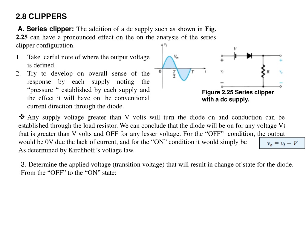
2.8 CLIPPERS A. Series clipper: The addition of a dc supply such as shown in Fig. 2.25 can have a pronounced effect on the on the anatysis of the series clipper configuration. 1. Take carful note of where the output voltage is defined. Try to develop on overall sense of the response by each supply noting the pressure established by each supply and the effect it will have on the conventional current direction through the diode. Any supply voltage greater than V volts will turn the diode on and conduction can be established through the load resistor. We can conclude that the diode will be on for any voltage Vi that is greater than V volts and OFF for any lesser voltage. For the OFF condition, the output would be 0V due the lack of current, and for the ON condition it would simply be As determined by Kirchhoff s voltage law. 2. Figure 2.25 Series clipper with a dc supply. 3. Determine the applied voltage (transition voltage) that will result in change of state for the diode. From the OFF to the ON state:
For the ON region the diodes is replaced by short circuit equivalent and Fig 2.26 Determining vo for the diode in the ON state. for the off region is an open circuit , ID = 0mA , VO = 0V. 4. It is often helpful to draw the output waveform directly below the applied voltage using the same scales for the horisontal axis and the vertical axis. For the ON conduction, output voltage has it s peak value: VOpeak = Vm - V
B. Parallel Clipper: The network of Fig. 2.27 is the simplest of parallel diode configurations with the output for the same inputs. The analysis of parallel configurations is very similar to that applied to series configurations. Figure 2.27 Response to a parallel clipper.
EXAMPLE: Determine vo for the network of Fig. 2.28. Figure 2.28 Solution: Step-1. The output is defined across the series combination of the 4V- Supply and the diode, not across resistor R. Step-2. The polarity of the dc supply and the direction of the diode strongly suggest that the diode will be in the on state for agood portion of the negative region of the input signal. In fact, It is interesting to note that since the outpu is directly across the series combination, Figure 2.29 Determining the transition level for.
