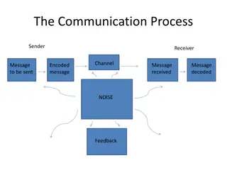
Understanding Digital Carrier Systems in Communication
Explore the concept of digital carrier systems in communication, covering topics such as amplitude shift keying (ASK), frequency shift keying (FSK), and demodulation processes. Learn how digital signals are transmitted over long distances effectively.

Download Presentation

Please find below an Image/Link to download the presentation.
The content on the website is provided AS IS for your information and personal use only. It may not be sold, licensed, or shared on other websites without obtaining consent from the author. Download presentation by click this link. If you encounter any issues during the download, it is possible that the publisher has removed the file from their server.
E N D
Presentation Transcript
Digital Carrier Systems K.S.V.SAMBASIVARAO K.S.V.SAMBASIVARAO HOD DEPT. OF ELECTRONICS PBSC COLLEGE Of A& S VIJAYAWADA
Digital carrier system: In digital communication the signal cannot be transmitted into space by radiation. The digital signal can only be send through wires, but it is not possible to send the digital signal through longer distance by using wires. Hence, continuous wave modulation is employed in which digital signal is again modulated by a higher frequency wave (carrier) for longer distance transmission. Since analog signal will have an advantage of sending digital (bits). Here we use a process called Keying (nothing but modulation in analog system).
classification For digital, the system is keyed by shifting one of the carriers namely amplitude, frequency and phase is varied in accordance with the instantaneous value the digital signal between the two levels (0 No carrier, 1 Carrier) Types of digital carrier systems: i)Amplitude shift keying (ASK) or On-Off Keying (OOK). ii)Frequency shift keying (FSK). iii) Phase shift keying (PSK).
ASK: The system is keyed by shifting the amplitude of the carrier between the two levels (0,1), then it is called ASK. Binary 1 stands for maximum amplitude. Binary 0 stands for minimum amplitude. Generation of ASK: The ASK signal can be generated by using simple multiplier circuit. The input for multiplier circuit is base based signal and a carrier. Here the carrier amplitude is shifted between the two levels depending upon the input base band signal. The output will be in the form V0= b (t) x A Cos ( ct + )
Demodulation The ASK signal which transmitted by radiation, it is the process to recover the baseband signal. Initially the carrier is recovered by the carrier recovery circuit. The recovered carrier must be in same phase and frequency to that of the carrier at the transmitter. The recovered carrier and ASK signal are multiplied in a multiplier circuit, We get, A b (t) Cos2( ct + ) = A b(t) The signal is given to low pass filter whose output is the base hand signal.
FSK: In this the system is keyed by shifting the frequency of the carrier between the two levels i.e one is other is low frequency (0) and high frequency (1). Then it is called FSK. Generation: To generate FSK two oscillators are used to have carrier frequency f1 & f2 depending on the input binary signal. The frequency of carrier is shifted between two levels f1 & f2. If b (t) =1 the output will be high frequency f1 , second multiplier output is zero. Similarly if b (t) =0 the output will be low frequency f2 , the first multiplier output is zero. The output of the multipliers is combined in the adder to get FSK. The disadvantage of the FSK, carrier must be generated at two different frequencies. The combined signal will be discontinuity in amplitude and phase.
Demodulation: To detect FSK signal, i.e., to recover the baseband signal. The receiver can be constructed by using two separate ASK detectors. From FSK signal the carrier frequencies f1 and f2 are recovered by using carrier recovery circuit. These frequencies are multiplied with FSK signal in two different multipliers, the output of these multipliers are added in a adder and given to a pulse generator circuit to recover the same baseband signal or binary signal.
PSK: The system is keyed by shifting [1,-1] the phase of the carrier between the 2 levels 00 and 1800 then it is called PSK. It is also known phase reversal key (PRK). Generation of PSK: The CKT for implementing BPSK is a balanced modulator , which is a multiplier CKT. The input baseband signal is first converted into polar-non return zero ( 1) & then given to a balanced modulator (Multiplier) to generate PSK signal. The o/p of balanced modulator is V0 = b (t). A Cos ( ct+ ) If b (t) =1; V0 = A Cos ( ct+ ) {in-phase} If b (t) =-1; V0 = - A Cos ( ct+ ) {out-phase by 1800} V0 = Cos = A Cos ( + ct+ )
Demodulation: The BPSK signal which is transmitted by radiation is the process to recover the base band signal. Initially, the carrier is recovered by using the carrier recovery CKT . It is also known as coherent detection. The o/p of the circuit is then given to a polar non- return zeros detector CKT. The final o/p of CKT is base band signal.
PULSE MODULATION Pulse modulation may be used to transmit the analog information such as continuous speech or data It is a system in which continuous waveforms are sampled at the regular intervals. The information regarding the signal is transmitted in the form of the pulses At the receiving end, the original waveforms may be re- constructed from the information regarding the samples. In pulse modulation, carrier signal is a discrete pulse train instead of sine wave. The modulation signal various amplitude width or position of these discrete pulses to get PAM (pulse amplitude modulation), PWM (pulse width modulation), and PPM (pulse position modulation) signals respectively.
:Sampling Theorem: It states that the sampling frequency (Fs) i.e., number of samples per second should be greater than or equal to twice the maximum frequency component (Fm) of the signal. Fs > 2Fm Nyquist Rate: The minimum possible value of sampling frequency is termed as Nyquist rate. According to sampling theorem, the nyquist rate is Fs min = 2Fm But, the minimum sampling frequency Fs is equal to 2Fm cannot be achieved in practice because of the difficulty in realizing the ideal filters. Practically we must use the sampling frequency which is more than twice the maximum frequency in baseband waveform.
PAM Generation In PAM system the signal is sampled at regular intervals and each sample is made proportional to amplitude of the signal at the instant of sampling. The pulses are then sent by either wire or cable which is used to modulate a carrier. It is very easy to generate and demodulate PAM. The signal to be converted to PAM is fed through switch which is controlled by pulse train. When pulse is present i.e., signal is at high level, switch closed. When pulse is absent i.e., signal is at low level switch is open. With this control action of switch we get pulse amplitude waveform at the output terminal of switch. The pulse amplitude modulated signal is passed through a pulse shaping network, which gives them flat tops as these output pulses can be used to frequency modulate the carrier to form PAM-FM system.
PAM Detection In the receiver, the pulses are detected by a standard FM demodulator. Then they are passed to an ordinary diode detector, which is followed by a low pass filter. If the cut-off frequency of this filter is greater than the highest signal frequency, but at the same time much less than the sampling frequency of the pulses, then the original signal can be recovered at the received end, without distortion.
PTM Pulse Time Modulation: In pulse time modulation, amplitude of pulse is held constant, whereas width of pulse is made proportional to amplitude of signal at the sampling instant. Then we have two types of pulse time modulation, viz. Pulse Width Modulation [PWM] and Pulse Position Modulation [PPM]. Since in both PWM and PPM, amplitude is held constant and does not carry information, amplitude limiters can be used. The amplitude limiters, similar to those used in FM, will clip off the portion of the signal corrupted by the noise and thus provide a good degree of noise immunity.
PWM Generation The PWM is also called pulse duration modulation or pulse length modulation. Def: The width of the pulse (carrier) is varied in accordance to the instantaneous value of the modulating signal. The principle of operation is that the amplitude and starting time of each pulse of a signal is kept constant while width of pulse is made proportional to amplitude of signal at that instant. :
. Generation of PWM
PWM Detection The received PWM signal is applied to the Schmitt trigger circuit. The Schmitt trigger circuit removes the noise in the PWM waveform. The regenerated PWM is then applied to the ramp generator and the synchronization pulse detector. The ramp generator produces ramp for the duration of pulses such that height of ramps are proportional to the widths of PWM pulses. The maximum ramp voltage is retained till the next pulse. On the other hand synchronous pulse detector produces reference pulses with constant amplitude and pulse width. These pulses are delayed by specific amount of delay . The delayed reference pulses and the output of ramp generator is added with help of adder. The output of adder is given to the level shifter. Here, negative offset shifts the waveform . Then the negative part of the waveform is clipped by rectifier. Finally, the output of rectifier is passed through low-pass filter to remove the modulating signal.
Advantages of PWM: Unlike, PAM, noise is less, since in PWM, amplitude is held constant. Signal and noise separation is very easy. Does not require synchronization between transmitter and receiver. Disadvantages of PWM: In PWM, the pulses are varying in width and therefore their power contents are variable. This requires that the transmitter must be able to handle the power contents of the pulse having maximum pulse width. Large bandwidth is required for the PWM communication as compared to PAM.
PPM In this system, the amplitude and width of the pulses are kept constant, while the position of each pulse, with reference to the position of a reference pulse, is changed according to the instantaneous sampled value of the modulating signal. Thus the transmitter has to send synchronizing pulses to keep the transmitter and receiver in synchronism. As the amplitude and width of the pulses are constant, the transmitter handles constant power output. Disadvantage of the PPM system is the need for transmitter-receiver synchronization. A pulse position modulation is obtained from pulse width modulation.
PPM generation It consists of the differentiator and a monostable multivibrator. The input to the differentiator is a PWM waveform. The differentiator generates positive and negative spikes corresponding to leading and trailing edges of the PWM waveform. Diode D1 is used to bypass the positive spikes. The negative spikes are used to the trigger monostable multivibrator. The monostable multivibrator then generates the pulses of same width and amplitude with reference to trigger to give pulse position modulated waveform.
PPM Detection In the case of pulse-position modulation, it is customary to convert the received pulses that vary in position to pulses that vary in length. One way to achieve this is shown in below fig.
The flip-flop circuit is set or turned ON (giving high output) when the reference pulse arrives. This reference pulse is generated by the reference pulse generator of the receiver with the synchronization signal from the transmitter. The flip-flop circuit is reset or turned OFF (giving low output) at the leading edge of the position modulated pulse. This repeats and we get PWM pulses at the output of the flip-flop. The PWM pulses are then demodulated by PWM demodulator to get original modulating signal. Advantages of PPM: PPM amplitude is held constant thus less noise interference. Signal and noise separation is very easy. Due to constant pulse widths and amplitudes, transmission power for each pulse is same. Disadvantages of PPM: Synchronization between transmitter and receiver is required. Large bandwidth is required as compared to PAM.
PCM PCM increases reliability by transmitting data in digital units. The accuracy of transmission then depends on the number of digits used in the code but is independent of equipment linearity. pulse-code modulation uses a binary code. The transmitter binary pulses have the same amplitude and same duration. Hence, like in FM reception, limiter can be used to reduce noise. Furthermore, even if the signals are highly corrupted by noise, or highly attenuated or distorted, all the receiver has to do is to determine the presence of the pulse, without paying attention to its amplitude, width or shape. The receiver has just to find whether the pulse is there or not. Receiver even under the most severe conditions of attenuation, noise, or distortion. Because of this simplicity in reception, PCM has replaced all other pulse communication systems. Even FM in analog systems is being replaced by PCM. This is especially true in satellite communication systems. With the advent of digital ICs, PCM has become very cheap and economical and easy for implementation.
PRINCIPLE OF OPERATION OF PCM PCM also uses the sampling process. In PCM, the peak-to-peak amplitude range which the signal to be transmitted, may have divided into a number of standard steps or levels. As these levels are transmitted in a binary code, the actual number of levels is always a power of 2. Each step is assigned a digital code number. The number of digits used in the binary code determines the total number of steps available and the accuracy of the transmitted value. For example, a 4 digit binary system provides a total of 16 steps, as shown in below table. Each step is assigned a binary code. If the signal amplitude is 6.8 V. It is transmitted as the digit 7, because 7V is the standard amplitude nearest to 6.8 V. If 16 levels [24] are used, 4 binary digits are required corresponding to a given standard level. Then digit 7, in above example. Will be sent as a series of pulses, corresponding to number 7. From the previous table, the number 7 is 0111, and could be sent as OPPP where P = Pulse and O = No pulse. Actually, it is often sent as a binary number back- to-front, i.e., as 1110, or PPPO, to make demodulation easier. Thus, in PCM, the signal is continuously sampled, quantized, coded, and transmitted, after each sample amplitude is converted to the nearest standard amplitude and into the corresponding back-to-front binary number.
Quantizing Noise: In quantizing, the actual amplitude at the sampling instant is not transmitted, but, its nearest standard level is transmitted in coded form. The quantizing process then introduces a certain amount of error in the transmitted signal, which is called quantizing error or quantizing noise. This error is small if a large number of standard levels are used for a given range of signal. A 5-place code would allow 32 steps [25] while a 7-digit code would result in 128 [27] steps, giving better than 1% accuracy. This 7-digit code, giving 128 steps, is a standard for transmitting voice signals in telephony. However, when more number of levels are used, more bits are required to be sent per step, requiring more bandwidth since the bandwidth required is proportional to the number of bits per second. Generation of PCM: The basic elements for the generation of pulse code modulation are shown in the Fig: the analog signal m (t) is passed through the anti-aliasing filter which avoids aliasing. Aliasing refers to the overlapping of parts of spectra and once such overlap is allowed to occur the spectra can no longer be separated by filtering. The output of anti-aliasing filter is sampled using sample and hold circuit. The flat top samples are then quantized and converted to digital numbers through an analog to digital converter.
Detection At the receiver, the signaling intelligence is extracted, and PCM is converted into corresponding PAM pulses which are then demodulated in the usual way. As PCM is highly immune to noise, amplitude modulation of PCM signal on RF carrier is quite common, so that the communication system become PCM-AM system. Working with very small signal levels (by comparison with the quantization interval) can introduce more errors. Companding can be used to increase the accuracy of such signals. This is the process of distorting the analogue signal in a controlled way before quantizing takes place, by compressing its larger values at the source and then expanding them at the receiving end. There are two standards used: A- law in Europe, and -law in the USA. The term companding was created by combining the terms COMpressing and exPANDING
Multiplex Transmission More efficient communication system can be obtained if a station transmits more than one message on the same carrier and on the same channel, or number of transmitters are transmitting simultaneously on the same channel. This process is known as multiplexing . There are two types of multiplexing Frequency Division Multiplexing [FDM] Time Division Multiplexing [TDM] Multiplexing requires that the signals be kept apart so that they do not interfere with each other, and thus they can be separated at the receiving end. This is accomplished by separating the signal either in frequency or time. Frequency Division Multiplexing (FDM): The most commonly method of modulation in FDM is single sideband modulation, which requires a bandwidth that is approximately equal to that of original message signal. The band pass filters following the modulators are used to restrict the band of each modulated wave to its prescribed range.
At the receiving end, band pass filters connected to the common channel separate the message signals on the frequency occupancy basis. Finally, the original message signals are recovered by individual demodulators
TDM In TDM, each signal to be transmitted [voice or telemetry data] is sampled sequentially and the resulting pulse code is used to modulate the carrier. Since only one signal modulates the carrier at any time, no added equipment and no increase in bandwidth is needed when multiplexing. Thus, in TDM, each signal occupies the entire bandwidth of the channel. However, each signal is transmitted for only a short period of time. The five signals are time division multiplexed. Each signal is allowed to use the channel for a fixed interval of time, called time slot. The five signals use the channel sequentially one after other. Once all the signals have been transmitted, the cycle repeats again and again, at a high rate of speed. The TDM system which is used to multiplex the five signals. A rotating switch called a commutator connects the output of each channel modulator to the communication channel input in turn. The commutator is realized with electronic switches since it has to rotate at high speed. The commutator remains at each contact for a fixed interval of time, which is the time slot allotted for each channel.
At the receiver, another switch, rotating in synchronism with the sending end commutator is used. This switch connects the pulses received to the appropriate demodulator circuits. For the proper operation of the system, absolute synchronism is very essential, between transmitter and receiver.