Understanding Different Instruction Formats in Computing
Instruction formats in computing include one-address, two-address, three-address, and zero-address instructions, each with specific ways of specifying operations and operands. One-address instructions utilize an implied accumulator register, while two-address and three-address instructions allow for operand and memory specification. Zero-address instructions are used in stack-organized computers for operations like PUSH and POP. Each format has its own advantages and use cases when executing operations like addition and multiplication.
Download Presentation

Please find below an Image/Link to download the presentation.
The content on the website is provided AS IS for your information and personal use only. It may not be sold, licensed, or shared on other websites without obtaining consent from the author. Download presentation by click this link. If you encounter any issues during the download, it is possible that the publisher has removed the file from their server.
E N D
Presentation Transcript
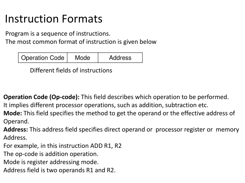
Instruction Formats Program is a sequence of instructions. The most common format of instruction is given below Operation Code Mode Address Different fields of instructions Operation Code (Op-code): This field describes which operation to be performed. It implies different processor operations, such as addition, subtraction etc. Mode: This field specifies the method to get the operand or the effective address of Operand. Address: This address field specifies direct operand or processor register or memory Address. For example, in this instruction ADD R1, R2 The op-code is addition operation. Mode is register addressing mode. Address field is two operands R1 and R2.
Evaluates X = (A + B) * (C + D) using Three Address Instructions Computers with three-address instruction formats can use each address field to specify either a processor register or a memory operand. ADD R1, A, B R1 M[A] + M[B] ADD R2, C, D R2 M[C] + M[D] MUL X, R1, R2 M[X] R1 * R2 It is assumed that the computer has two processor registers, R1 and R2. The symbol M[A] denotes the operand at memory address symbolized by A.
Evaluates X = (A + B) * (C + D) using Two Address Instructions Here again each address field can specify either a processor register or a memory word. MOV R1, A R1 M[A] ADD R1, B R1 R1 + M[B] MOV R2, C R2 M[C] ADD R2, D R2 R2 + M[D] MUL Rl , R2 R1 R1 * R2 MOV X, R1 M[X] R1 The MOV instruction moves or transfers the operands to and from memory and processor registers. The first symbol listed in an instruction is assumed to be both a source and the destination where the result of the operation is transferred.
Evaluates X = (A + B) * (C + D) using One Address Instructions One-address instructions use an implied accumulator (AC) register for all data manipulation. For multiplication and division there is a need for a second register. However, here we will neglect the second register and assume that the AC contains the result of all operations. LOAD A AC M[A] ADD B AC AC + M[B] STORE T M[T] AC LOAD C AC M[C] ADD D AC AC + M[D] MUL T AC AC * M[T] STORE X M[X] AC All operations are done between the AC register and a memory operand. T is the address of a temporary memory location required for storing the intermediate result.
Evaluates X = (A + B) * (C + D) using Zero Address Instructions A stack-organized computer does not use an address field for the instructions ADD and MUL. The PUSH and POP instructions, however, need an address field to specify the operand that communicates with the stack. (TOS stands for top of stack.) PUSH A TOS A PUSH B TOS B ADD TOS (A + B) PUSH C TOS C PUSH D TOS D ADD TOS (C + D) MUL TOS (A + B) * (C + D) POP X M[X] TOS
Evaluates X = (A - B) / C using Three Address Instructions Computers with three-address instruction formats can use each address field to specify either a processor register or a memory operand. SUB R1, A, B R1 M[A] - M[B] DIV X, R1, C M[X] R1 / M[C] Evaluates X = (A - B) / C using Two Address Instructions Here again each address field can specify either a processor register or a memory word. MOV R1, A R1 M[A] SUB R1, B R1 R1 - M[B] DIV R1 , C R1 R1 / M[C] MOV X, R1 M[X] R1
Evaluates X = (A - B) / C using One Address Instructions One-address instructions use an implied accumulator (AC) register for all data manipulation. For multiplication and division there is a need for a second register. However, here we will neglect the second register and assume that the AC contains the result of all operations. LOAD A AC M[A] SUB B AC AC - M[B] DIV C AC AC / M[C] STORE X M[X] AC
Evaluates X = (A - B) / C using Zero Address Instructions A stack-organized computer does not use an address field for the instructions ADD and MUL. The PUSH and POP instructions, however, need an address field to specify the operand that communicates with the stack. (TOS stands for top of stack.) PUSH A TOS A PUSH B TOS B SUB TOS (A - B) PUSH C TOS C DIV TOS (A - B) / C POP X M[X] TOS
Evaluates X = (A + B) / (C - D) using Three Address Instructions Computers with three-address instruction formats can use each address field to specify either a processor register or a memory operand. ADD R1, A, B R1 M[A] + M[B] SUB R2, C, D R2 M[C] - M[D] DIV X, R1, R2 M[X] R1 / R2 It is assumed that the computer has two processor registers, R1 and R2. The symbol M[A] denotes the operand at memory address symbolized by A.
Evaluates X = (A + B) / (C - D) using Two Address Instructions Here again each address field can specify either a processor register or a memory word. MOV R1, A R1 M[A] ADD R1, B R1 R1 + M[B] MOV R2, C R2 M[C] SUB R2, D R2 R2 - M[D] DIV Rl , R2 R1 R1 / R2 MOV X, R1 M[X] R1 The MOV instruction moves or transfers the operands to and from memory and processor registers. The first symbol listed in an instruction is assumed to be both a source and the destination where the result of the operation is transferred.
Evaluates X = (A + B) / (C - D) using One Address Instructions One-address instructions use an implied accumulator (AC) register for all data manipulation. For multiplication and division there is a need for a second register. However, here we will neglect the second register and assume that the AC contains the result of all operations. LOAD C AC M[C] SUB D AC AC - M[D] STORE T M[T] AC LOAD A AC M[A] ADD B AC AC + M[B] DIV T AC AC / M[T] STORE X M[X] AC All operations are done between the AC register and a memory operand. T is the address of a temporary memory location required for storing the intermediate result.
Evaluates X = (A + B) / (C - D) using Zero Address Instructions A stack-organized computer does not use an address field for the instructions ADD and MUL. The PUSH and POP instructions, however, need an address field to specify the operand that communicates with the stack. (TOS stands for top of stack.) PUSH A TOS A PUSH B TOS B ADD TOS (A + B) PUSH C TOS C PUSH D TOS D SUB TOS (C - D) MUL TOS (A + B) / (C - D) POP X M[X] TOS
Addressing mode The different ways for specifying the locations of instruction operands are known as addressing modes. 1. Implied address mode: In this mode operands are implicitly defined in the instruction. Ex: i) CMA(Complement the content of accumulator) 1 0 1 1 0 0 1 0 AC After CMA instruction AC 0 1 0 0 1 1 0 1 ii) RLC (Rotate Accumulator Left) AC 1 0 0 1 1 1 1 0 After RLC instruction AC 0 0 1 1 1 1 0 1
Addressing mode contd. 2. Immediate address mode: In this mode operands are directly specified in the instruction. Ex: i) MVI R1,06 (Move Immediate the value 06 into register R1) 06 R1 ii)ADI 08 (Add immediate the content of accumulator with 08 value) 3. Register address mode: In this mode the operands are the contents of a processor register. The name of the Register is given in the instruction. Ex: i) MOV R1,R2 (The content of Register R2 is copied to Register R1) AC=AC + 08 ii) ADD R1,R2 (The content of Register R1 is added with the content of Register R2) 4. Direct (absolute) address mode: In this mode the operand is in a memory location; the address of this location is directly specified in the instruction. Ex: i) LDA 9000 (Load the accumulator with the content of memory location 9000). 9000 20 AC 20 ii) STA 9500 (Store the content of accumulator in the memory location 9500). AC 30 9500 30
Addressing mode contd. 5. Indirect address mode: In this mode the address of the operand is indirectly specified in the register or memory location. If the address of the operand is stored in the register then it is called Register Indirect mode. If the address of the operand is stored in the memory location then it is called Memory Indirect mode. Ex: i) ADD R1,(R) (The content of register R1 is added with the content of memory location which is stored in R) 06 R1 9400 R 9400 30 R1= R1 + (9400) ii) ADD R1,(2000) (The content of register R1 is added with the content of memory location which is stored in 2000) 9500 2000 06 9500 80 R1 R1= R1 + (9500)
Addressing mode contd. 6. Index address mode: In this mode the effective address is calculated by adding the content of index register with the address part of the instruction. Ex: i) MOV R1,RB (20) 9400 RB effective address = 9400 + 20 = 9420 9400 50 RB holds the base address 20 R1 70 9420 70 ii) MOV R1, 9000(RI) 20 RI effective address = 9000 + 20 = 9020 9000 30 RI holds the index value 20 R1 80 9020 80
Addressing mode contd. 7.Auto increment and auto decrement address mode: The effective address of the operand is the contents of a register specified in the instruction. After accessing the operand, the contents of this register are Automatically incremented to point to the next operand in memory. We denote the Auto increment mode by putting the specified register in parentheses, to show that the contents of the register are used as the effective address, followed by a plus sign to indicate that these contents are to be incremented after the operand is accessed. Thus, the Auto increment mode is written as (Ri)+ The contents of a register specified in the instruction are first automatically decremented and are then used as the effective address of the operand. We denote the Auto decrement mode by putting the specified register in parentheses, preceded by a minus sign to indicate that the contents of the register are to be decremented before being used as the effective address. Thus, we write (Ri)
