Understanding Data Transfer and Interfacing in Computer Systems
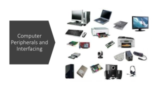
Data transfer in computer systems involves interfacing between the central processing unit (CPU) and various peripherals such as keyboards, CRT terminals, and cassette tapes. This process enables the exchange of information between internal storage and external input/output (I/O) devices. Interface modules facilitate communication by decoding device addresses and commands, synchronizing data flow, and supervising transfer rates. Two main types of interfacing for I/O devices are I/O mapped I/O and memory-mapped I/O. Each has its own characteristics and suitable applications, impacting data transfer efficiency and system performance.
Download Presentation

Please find below an Image/Link to download the presentation.
The content on the website is provided AS IS for your information and personal use only. It may not be sold, licensed, or shared on other websites without obtaining consent from the author. Download presentation by click this link. If you encounter any issues during the download, it is possible that the publisher has removed the file from their server.
E N D
Presentation Transcript
INTERFACING Giving input (or) retrieving output from the Mp is only through some peripherals, such as, keyboards, CRT terminal, cassette tape, etc. So mapping of data transfer from Mp to peripherals is INTERFACING.
* Provides a method for transferring information between internal storage (such as memory and CPU registers) and external I/O devices * Resolves the differences between the computer and peripheral devices - Peripherals - Electromechanical Devices CPU or Memory - Electronic Device - Data Transfer Rate Peripherals - Usually slower CPU or Memory - Usually faster than peripherals Some kinds of Synchronization mechanism may be needed - Unit of Information Peripherals - Byte CPU or Memory - Word - Operating Modes Peripherals - Autonomous, Asynchronous CPU or Memory - Synchronous
Data Address Control Processor Interface Interface Interface Interface Keyboard and Magnetic disk Magnetic tape Printer terminal Each peripheral has an interface module associated with it. Interface has the following role: - Decodes the device address (device code) - Decodes the commands (operation) - Provides signals for the peripheral controller - Synchronizes the data flow and supervises the transfer rate between peripheral and CPU or Memory
INTERFACING I/O Devices It is of 2 types: (I/O DATA TRANSFER) 1. I/O MAPPED I/O, & 2. MEMORY MAPPED I/O.
MAPPING 1. I/O MAPPED I/O: Same address may be for memory or I/O device. So Intel 8085 issues IO/M signal for the purpose. Two extra instructions: a) IN , b) OUT. Suitable for a large system. 2. MEMORY MAPPED I/O: Only one address space. I/O device also treated as memory location. Suitable for small system.
Characteristics Memory-Mapped Peripheral-mapped Device address 16 bit 8 bit Control signals MEMR, MEMW IOR, IOW Instructions All memory related MOV, ADD, SUB, LOAD, IN, OUT Data transfer Between any register and I/O Only between I/O and AX Max no. of I/O Memory range 256 input and, 256 output Execution speed Slow Faster H/W More Less Other features Arithmetic or Logical operations directly performed. Not Available.
I/O data Port A register Bidirectional Bus buffers data bus I/O data Port B register I/O CPU Chip select CS Device Register select Control register Control RS1 Timing Register select and Control RS0 I/O read RD Status Status I/O write register WR CS RS1 RS0 Register selected 0 x x None - data bus in high-impedence 1 0 0 Port A register 1 0 1 Port B register 1 1 0 1 1 1 Control reg. Status reg.
Data Transmission Most digital messages are longer than just a few bits. It is neither practical nor economic to transfer all bits of a long message simultaneously. The message is broken into smaller parts and transmitted sequentially. Bit-serial transmission conveys a message one bit at a time through a channel. Each bit represents a part of the message.
Bit-serial Data Transmission The individual bits are then reassembled at the destination to compose the message. In general, one channel will pass only one bit at a time. Thus, bit-serial transmission is necessary in data communications if only a single channel is available. Bit-serial transmission is normally just called serial transmission and is the chosen communications method in many computer peripherals.
Byte-serial Data Transmission Byte-serial transmission conveys eight bits at a time through eight parallel channels. Although the raw transfer rate is eight times faster than in bit- serial transmission, eight channels are needed, and the cost may be as much as eight times higher to transmit the message. When distances are short, both techniques may be feasible and economic to use parallel channels in return for high data rates. The popular Centronics printer interface is a case where byte- serial transmission is used.
Byte Transmission As another example, it is common practice to use a 16-bit-wide data bus to transfer data between a microprocessor and memory chips. This provides the equivalent of 16 parallel channels. On the other hand, when communicating with a timesharing system over a modem, only a single channel is available, and bit-serial transmission is required.
Synchronization Two types of transmission: Asynchronous Synchronous Asynchronous Transmission In asynchronous transmission, each character is transmitted separately with separate synchronization information. This type of transmission is often used in situation when characters may be generated at random intervals, such as when a user types at a terminal. In asynchronous transmission, all of the bits that comprise a character are framed and then sent as a single transmission string.
ASYNCHRONOUS DATA TRANSFER Synchronous and Asynchronous Operations 1. Synchronous Operations:- All devices derive the timing information from clock line. 2. Asynchronous Operations :- No common clock Asynchronous data transfer between two independent units requires that control signals be transmitted between the communicating units to indicate the time at which data is being transmitted
Two Asynchronous Data Transfer methods :- 1. Strobe Pulse:- It is supplied by one unit to indicate the other unit when the transfer has to occur. 2. Handshaking :- A control signal is accompanied with each data being transmitted to indicate the presence of data. The receiving unit responds with another control signal to acknowledge receipt of data
Asynchronous Transmission Start and Stop Bit Framing The clocks of the transmitter and the receiver are not continually synchronized. But the receiver needs to know when the character begins and ends. For this reason, the character's bit string is framed with start and stop bits. The start bit reset the receiver's clock so that it matches the transmitter's. The clock only needs to be accurate enough to stay in sync for the next 8 to 11 ticks. At least one stop bit is added to mark the end of the character and allow recognition of the next start bit.
Strobe Control This method of asynchronous data transfer uses a single control line to time each transfer. The strobe may be activated by the source or the destination unit. i) Source Initiated Data Transfer: The data bus carries the information from source to destination. The strobe is a single line. The signal on this line informs the destination unit when a data word is available in the bus. The strobe signal is given after a brief delay, after placing the data on the data bus. A brief period after the strobe pulse is disabled the source stops sending the data.
(ii) Destination Initiated Data Transfer: In this case the destination unit activates the strobe pulse informing the source to send data. The source places the data on the data bus. The transmission is stopped briefly after the strobe pulse is removed. The disadvantage of the strobe is that the source unit that initiates the transfer has no way of knowing whether the destination unit has received the data or not. Similarly if the destination initiates the transfer it has no way of knowing whether the source unit has placed data on the bus or not. This difficulty is solved by using hand shaking method of data transfer.
Asynchronous Data Transfer HANDSHAKING Strobe Methods Source-Initiated The source unit that initiates the transfer has no way of knowing whether the destination unit has actually received data Destination-Initiated The destination unit that initiates the transfer no way of knowing whether the source has actually placed the data on the bus To solve this problem, the HANDSHAKE method introduces a second control signal to provide a Reply to the unit that initiates the transfer
Asynchronous Data Transfer SOURCE-INITIATED TRANSFER USING HANDSHAKE Data bus Data valid Source unit Destination unit Block Diagram Data accepted Data bus Valid data Timing Diagram Data valid Data accepted Source unit Sequence of Events Destination unit Place data on bus. Enable data valid. Accept data from bus. Enable data accepted Disable data valid. Invalidate data on bus. Disable data accepted. Ready to accept data (initial state).
DESTINATION-INITIATED TRANSFER USING HANDSHAKE Data bus Data valid Block Diagram Source unit Destination unit Ready for data Ready for data Timing Diagram Data valid Data bus Valid data Sequence of Events Destination unit Ready to accept data. Enable ready for data. Source unit Place data on bus. Enable data valid. Accept data from bus. Disable ready for data. Disable data valid. Invalidate data on bus
Asynchronous Transmission Error Detection One way to detect errors in asynchronous transmission is to add an extra bit, called a parity bit, to the end of each character in a frame. Summary: Uncomplicated and inexpensive but slow and Overhead for each character.
Four Different Types of Transfer Asynchronous serial transfer Synchronous serial transfer Asynchronous parallel transfer Synchronous parallel transfer Asynchronous Serial Transfer - Employs special bits which are inserted at both ends of the character code - Each character consists of three parts; Start bit; Data bits; Stop bits. 1 1 0 0 0 1 0 1 Stop Start Character bits bits
Synchronous Transmission In some application it is necessary for large blocks of data, such as the contents of a disk file, to be transmitted. Synchronous transmission is more efficient method of transmitting large block of data. The data are usually buffered and transmitted as an entire message or frame. For this reason, clocks on both sides must maintain synchronization during transmission. This is accomplished in one of two ways: 1. A separate synchronizing signal, a clock, can be constantly transmitted 2. Clocking can be included in the data signal
Synchronous Transmission Error Detection Cyclic Redundancy Check (CRC) is often used in synchronous transmission. The CRC process subjects the block of data to an algorithm that computes a result based on its contents. This result is appended to the block prior to transmission. On the receiving side, the same algorithm is used and the result is compared with the CRC field. Any difference is assumed to mean frame damage during transmission and retransmission is repeated. More efficient, higher speed and improved error detection, But expensive and complex transmitter/receiver circuitry.
Communication Modes Three types of communication modes: simple, half-duplex, and full-duplex. Simplex One way transmitting, like Radio station. One transmitter, and the rest are receivers.
Hall-Duplex & Full-Duplex Half-Duplex Alternating two-way transmit and receive. When one is transmitting, other is listening, then one can transmit after a quiet on the channel. Full-Duplex Simultaneous transmit and receive at the same time. Of course, one frequency for transmitting, other for receiving.
Transmit data Transmitter register Shift register Bidirectional data bus Bus buffers Transmitter clock Control Transmitter register control and clock Chip select CS Internal Bus Receiver clock Status Receiver CS RS Oper. Register selected RS Timing register control and clock 0 x x None and I/O read 1 0 WR Transmitter register RD Control 1 1 WR Control register Receive data I/O write 1 0 RD Receiver register WR Receiver Shift 1 1 RD Status register register register
Data Transfer Modes of Transfer Programmed I/O Priority Interrupt Direct Memory Access Input-Output Processor
Modes Of Data Transfer Three types of data transfer modes : Program Controlled I/O: uses programming to transfer data , every item is initiated by instructions in the program Interrupt I/O: this method avoids the wait loop. In this scheme the i/o device initiates the transfer instead of the processor Direct Memory Access (DMA): in this mode of transfer large blocks of data directly between external devices and main memory
Programmed - I/O device to CPU
Initial Operations: 1. 2. 3. 4. 5. Clear lower level mask reg. Clear interrupt status bit IST. Save contents of processor reg. Set IEN. Proceed with Service routine. Final operations: 1. 2. 3. Clear IEN Restore contents of Processor reg. Clear bit in Interrupt refering to interrupt that has been serviced. Set Lower-level priority bits in Mask reg. Restore return address into PC and set IEN 4. 5.
Direct Memory Access Interrupt driven and programmed I/O require active CPU intervention Transfer rate is limited CPU is tied up DMA is the answer Direct Memory Access is a method of transferring data between peripherals and memory without using the CPU.
DMA Process Data is transferred between memory and disk directly without involving the processor Interrupt still tells CPU when such a transfer has started and finished. DMA transfers CPU tells the device controller operation to perform and addresses involved. Device controller then carries out the operation without bothering the CPU using DMA Bus controller arbitrates for the bus. Device controller informs the CPU when complete via an interrupt
DMA Modes DMA can operate in one of two modes Byte Mode DMAC takes over the bus for each byte of data to be transferred & then returns control to CPU Burst Mode A block of data is transferred before returning bus control to CPU Choice depends on the speed at which data is arriving & whether a particular application will allow the CPU to be locked off the bus for the duration of block transfer
