UML Package Diagrams and Components in Software Design
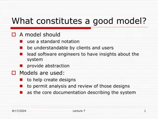
UML package diagrams are essential in organizing model elements such as use cases and classes into groups for a better structure in system modeling. They help in providing a high-level overview of requirements and architecture, logically modularizing complex diagrams, and indicating dependencies between packages. Guidelines for naming packages, simplifying diagrams, maintaining cohesion, and avoiding cyclic dependencies are crucial in effective package diagram design.

Download Presentation

Please find below an Image/Link to download the presentation.
The content on the website is provided AS IS for your information and personal use only. It may not be sold, licensed, or shared on other websites without obtaining consent from the author.If you encounter any issues during the download, it is possible that the publisher has removed the file from their server.
You are allowed to download the files provided on this website for personal or commercial use, subject to the condition that they are used lawfully. All files are the property of their respective owners.
The content on the website is provided AS IS for your information and personal use only. It may not be sold, licensed, or shared on other websites without obtaining consent from the author.
E N D
Presentation Transcript
UML Package and Component Diagram L6 3-3-2020 Package and component
Package diagram Package is a namespace used to group together elements that are semantically related and might change together. It is a general purpose mechanism to organize elements into groups to provide better structure for system model.
Package Diagrams A package diagram can be applied to any UML diagram. A package is a construct that enables you to organize model elements, such as use cases or classes, into groups. Create a package diagram to: Depict a high-level overview of your requirements (overviewing a collection of UML Use Case diagrams) Depict a high-level overview of your architecture/design (overviewing a collection of UML Class diagrams). To logically modularize a complex diagram.
Models, Views, Diagrams (Package Diagram)
Package Diagrams Packages appear as rectangles with small tabs (file folder) at the top. The package name is on the tab or inside the rectangle. The dotted arrows are dependencies. One package depends on another if changes in the other could possibly force changes in the first. Packages are the basic grouping construct with which you may organize UML models to increase their readability
General Guidelines Give Packages Simple, Descriptive Names Apply Packages to Simplify Diagrams Packages Should be Cohesive Indicate Architectural Layers With Stereotypes on Packages Avoid Cyclic Dependencies Between Packages Package Dependencies Should Reflect Internal Relationships
Package: Can be shown as Package member(s) are not shown inside the package. Package org.hibernate
Package: Package org.hibernate contains SessionFactory and Session. Package Member can be shown inside the package.
Package: Members of the package may be shown outside of the package by branching lines. Package org.hibernate contains interfaces Session and SessionFactory. nesting
Package: Nested packages. Qualifier for Graphics class is Java::Utilities::Graphics
Package: Visibility of Owned and Import element. "+" for public and "-" for private or helper class. All elements of Library Domain package are public except for Account.
Relationships: Dependency Generalization Refinement
Use Case Package Diagram(example): Use case Package Diagram Use case Diagram
Class Package Diagram class Package Diagram class Diagram
When to use Package Diagram ??? A large complex project may be based on large number of classes. Without some way to organize those classes, it will be impossible to relate and understand their responsibilities. Packages create a structure for classes or other UML elements by grouping related elements.
Component Diagrams Shows various components in a system and their dependencies, interfaces Explains the structure of a system Usually a physical collection of classes Similar to a Package Diagram in that both are used to group elements into logical structures With Component Diagrams all of the model elements are private with a public interface whereas Package diagrams only display public items.
UML component diagrams describe software components and their dependencies to each others. A component is an autonomous unit within a system. The components can be used to define software systems of arbitrary size and complexity UML component diagrams enable to model the high-level software components, and the interfaces to those components Important for component-based development (CBD) Component and subsystems can be flexibly REUSED and REPLACED Has one or more provided and required interfaces Its internals are hidden and inaccessible A component is encapsulated Its dependencies are designed such that it can be treated as independently as possible
A dependency elements if changes to the definition of one element may cause changes to the other Component Diagrams are often referred to as wiring diagrams The wiring of components represented on diagrams by means of components and dependencies between them exists between two can be
Component Diagram Notation Components are shown as rectangles with two tabs at the upper left Dashed arrows indicate dependencies Circle and solid line indicates an interface to the component
or.. A component is shown as a rectangle with A keyword <<component>> as steriotype Optionally, in the right hand corner a component icon can be displayed A component icon is a rectangle with two smaller rectangles jutting out from the left-hand side This symbol is a visual stereotype The component name Components can be labelled with a stereotype there are a number of standard stereotypes ex: <<entity>>, <<subsystem>>
Component ELEMENTS A component can have Interfaces An interface represents a declaration of a set of operations and obligations Usage dependencies A usage dependency is relationship which one element requires another element for its full implementation Ports Port represents an interaction point between a component and its environment Connectors Connect two components Connect the external contract of a component to the internal structure
INTERFACE A component defines its behaviour in terms of provided and required interfaces An interface Is the definition of a collection of one or more operations Provides only the operations but not the implementation Implementation is normally provided by a class/ component In complex systems, the physical implementation is provided by a group of classes rather than a single class
INTERFACE May be shown using a rectangle symbol with a keyword <<interface>> preceding the name For displaying the full signature, the interface rectangle can be expanded to show details Interfaces can be: Provided Required
INTERFACE A provided interface Characterize services that the component offers to its environment Is modeled using a ball, labelled with the name, attached by a solid line to the component A required interface Characterize services that the component expects from its environment Is modeled using a socket, labelled with the name, attached by a solid line to the component In UML 1.x were modeled using a dashed arrow
INTERFACE Where two components/classes provide and require the same interface, these two notations may be combined The ball-and-socket notation hint at that interface in question serves to mediate interactions between the two components If an interface is shown using the rectangle symbol, we can use an alternative notation, using dependency arrows
INTERFACE In a system context where there are multiple components that require or provide a particular interface, a notation abstraction can be used that combines by joining the interfaces A component Specifies a CONTRACT of the services that it provides to its clients and that it requires from others components in terms of its provided and required interfaces It can be replaced with other components The system can be extended
DEPENDENCIES Components can be connected by usage dependencies Usage Dependency A usage dependency is relationship which one element requires another element for its full implementation Is a dependency in which the client requires the presence of the supplier Is shown as dashed arrow with a <<use>> keyword The arrowhead points from the dependent component to the one of which it is dependent
A component have an external view and an internal view An external view (or black box view) shows publicly visible properties and operations An external view of a component is by means of interface symbols sticking out of the component box The interface can be listed in the compartment of a component box
INTERNAL VIEW An internal, or white box view of a component is where the realizing classes/components are nested within the component shape Realization is a relationship between two set of model elements One represents a specification The other represent an implementation for the specification
INTERNAL VIEW The internal class that realize the behavior of a component may be displayed in an additional compartment Compartments can also be used to display parts, connectors or implementation artifacts An artifact is the specification of a phisycal piece of information
INTERNAL VIEW Components can be built recursively
CONNECTORS Two kinds of connectors: Delegation Assembly ASSEMBLY CONNECTOR A connector between 2 components defines that one component provides the services that another component requires It must only be defined from a required interface to a provided interface An assembly connector is notated by a ball-and-socket connection This notation allows for proper graphical wiring of components
CONNECTORS DELEGATION CONNECTOR Links the external contract of a component to the internal realization Represents the forwarding of signals It must only be defined between used interfaces or ports of the same kind
Component Example - Linking Linking components with dependencies


:")
:")