System Modeling in Software Engineering
1
C
S
2
8
1
–
I
n
t
r
o
d
u
c
t
i
o
n
t
o
S
o
f
t
w
a
r
e
E
n
g
i
n
e
e
r
i
n
g
S
y
s
t
e
m
M
o
d
e
l
i
n
g
S
y
s
t
e
m
M
o
d
e
l
i
n
g
I
n
t
r
o
d
u
c
t
i
o
n
C
o
n
t
e
x
t
m
o
d
e
l
s
I
n
t
e
r
a
c
t
i
o
n
m
o
d
e
l
s
S
t
r
u
c
t
u
r
a
l
m
o
d
e
l
s
B
e
h
a
v
i
o
r
a
l
m
o
d
e
l
s
2
Chapter 5 System modeling
S
y
s
t
e
m
M
o
d
e
l
i
n
g
I
I
t
t
i
s
t
h
e
p
r
o
c
e
s
s
o
f
d
e
v
e
l
o
p
i
n
g
a
b
s
t
r
a
c
t
m
o
d
e
l
s
o
f
a
s
y
s
t
e
m
,
w
i
t
h
e
a
c
h
m
o
d
e
l
p
r
e
s
e
n
t
i
n
g
a
d
i
f
f
e
r
e
n
t
v
i
e
w
o
r
p
e
r
s
p
e
c
t
i
v
e
o
f
t
h
a
t
s
y
s
t
e
m
(
e
.
g
.
s
t
r
u
c
t
u
r
a
l
,
b
e
h
a
v
i
o
r
a
l
…
,
e
t
c
.
)
.
I
I
t
t
h
e
l
p
s
t
h
e
a
n
a
l
y
s
t
t
o
u
n
d
e
r
s
t
a
n
d
t
h
e
f
u
n
c
t
i
o
n
a
l
i
t
y
o
f
t
h
e
s
y
s
t
e
m
a
n
d
m
o
d
e
l
s
a
r
e
u
s
e
d
t
o
c
o
m
m
u
n
i
c
a
t
e
w
i
t
h
c
u
s
t
o
m
e
r
s
.
I
I
t
t
h
a
s
n
o
w
c
o
m
e
t
o
m
e
a
n
r
e
p
r
e
s
e
n
t
i
n
g
a
s
y
s
t
e
m
u
s
i
n
g
a
g
r
a
p
h
i
c
a
l
n
o
t
a
t
i
o
n
,
s
u
c
h
a
s
t
h
e
U
n
i
f
i
e
d
M
o
d
e
l
i
n
g
L
a
n
g
u
a
g
e
(
U
M
L
)
.
The most important of a system model is that it
leaves out
detail
.
3
Chapter 5 System modeling
I
n
t
r
o
d
u
c
t
i
o
n
t
o
S
y
s
t
e
m
M
o
d
e
l
i
n
g
–
C
o
n
t
.
Models of the
existing system
are used during
requirements engineering to clarify what the
existing
system does, its strengths and weaknesses
Basis for
the new system requirements.
Models of the
new system
are used during
requirements engineering to help
explain the proposed
requirements to other system stakeholders
. Engineers
use these models to discuss design proposals and to
document the system for implementation.
In a
model-driven engineering
process, it is possible to
generate a complete or partial system
implementation
from the system model.
4
Chapter 5 System modeling
E
x
a
m
p
l
e
s
:
A
s
a
m
e
a
n
s
o
f
f
a
c
i
l
i
t
a
t
i
n
g
d
i
s
c
u
s
s
i
o
n
a
b
o
u
t
a
n
e
x
i
s
t
i
n
g
o
r
p
r
o
p
o
s
e
d
s
y
s
t
e
m
.
I
n
c
o
m
p
l
e
t
e
a
n
d
i
n
c
o
r
r
e
c
t
m
o
d
e
l
s
a
r
e
O
K
a
s
t
h
e
i
r
r
o
l
e
i
s
t
o
s
u
p
p
o
r
t
d
i
s
c
u
s
s
i
o
n
.
A
s
a
w
a
y
o
f
d
o
c
u
m
e
n
t
i
n
g
a
n
e
x
i
s
t
i
n
g
s
y
s
t
e
m
.
M
o
d
e
l
s
s
h
o
u
l
d
b
e
a
n
a
c
c
u
r
a
t
e
r
e
p
r
e
s
e
n
t
a
t
i
o
n
o
f
t
h
e
s
y
s
t
e
m
b
u
t
n
e
e
d
n
o
t
b
e
c
o
m
p
l
e
t
e
.
A
s
a
d
e
t
a
i
l
e
d
s
y
s
t
e
m
d
e
s
c
r
i
p
t
i
o
n
t
h
a
t
c
a
n
b
e
u
s
e
d
t
o
g
e
n
e
r
a
t
e
a
s
y
s
t
e
m
i
m
p
l
e
m
e
n
t
a
t
i
o
n
.
M
o
d
e
l
s
h
a
v
e
t
o
b
e
b
o
t
h
c
o
r
r
e
c
t
a
n
d
c
o
m
p
l
e
t
e
.
5
Chapter 5 System modeling
S
y
s
t
e
m
P
e
r
s
p
e
c
t
i
v
e
s
A
n
e
x
t
e
r
n
a
l
p
e
r
s
p
e
c
t
i
v
e
:
w
h
e
r
e
y
o
u
m
o
d
e
l
t
h
e
c
o
n
t
e
x
t
o
r
e
n
v
i
r
o
n
m
e
n
t
o
f
t
h
e
s
y
s
t
e
m
.
A
s
t
r
u
c
t
u
r
a
l
p
e
r
s
p
e
c
t
i
v
e
:
w
h
e
r
e
y
o
u
m
o
d
e
l
t
h
e
o
r
g
a
n
i
z
a
t
i
o
n
o
f
a
s
y
s
t
e
m
o
r
t
h
e
s
t
r
u
c
t
u
r
e
o
f
t
h
e
d
a
t
a
t
h
a
t
i
s
p
r
o
c
e
s
s
e
d
b
y
t
h
e
s
y
s
t
e
m
.
A
n
i
n
t
e
r
a
c
t
i
o
n
p
e
r
s
p
e
c
t
i
v
e
:
w
h
e
r
e
y
o
u
m
o
d
e
l
t
h
e
i
n
t
e
r
a
c
t
i
o
n
s
b
e
t
w
e
e
n
a
s
y
s
t
e
m
a
n
d
i
t
s
e
n
v
i
r
o
n
m
e
n
t
,
o
r
b
e
t
w
e
e
n
t
h
e
c
o
m
p
o
n
e
n
t
s
o
f
a
s
y
s
t
e
m
.
A
b
e
h
a
v
i
o
r
a
l
p
e
r
s
p
e
c
t
i
v
e
:
w
h
e
r
e
y
o
u
m
o
d
e
l
t
h
e
d
y
n
a
m
i
c
b
e
h
a
v
i
o
r
o
f
t
h
e
s
y
s
t
e
m
a
n
d
h
o
w
i
t
r
e
s
p
o
n
d
s
t
o
e
v
e
n
t
s
.
6
Chapter 5 System modeling
You may develop different models to represent the system from
different perspectives
:
F
i
v
e
K
e
y
T
y
p
e
s
o
f
U
M
L
D
i
a
g
r
a
m
s
Activity
diagrams, which show the activities involved in a
process or in data processing .
Use case
diagrams, which show the
interactions
between a system and its environment.
Sequence
diagrams, which show
interactions
between
actors and the system and between system components.
Class
diagrams, which show the object classes in the
system and the
associations
between these classes.
State
diagrams, which show how the system reacts to
internal and external
events
.
7
Chapter 5 System modeling
M
o
d
e
l
s
o
f
a
S
y
s
t
e
m
1.
Context models
2.
Interaction models
3.
Structural models
4.
Behavioral models
8
Chapter 5 System modeling
S
S
y
y
s
s
t
t
e
e
m
m
m
m
o
o
d
d
e
e
l
l
i
i
n
n
g
g
i
s
t
h
e
p
r
o
c
e
s
s
o
f
d
e
v
e
l
o
p
i
n
g
a
b
s
t
r
a
c
t
m
o
d
e
l
s
o
f
a
s
y
s
t
e
m
,
w
i
t
h
e
a
c
h
m
o
d
e
l
p
r
e
s
e
n
t
i
n
g
a
d
i
f
f
e
r
e
n
t
v
i
e
w
o
r
p
e
r
s
p
e
c
t
i
v
e
o
f
t
h
a
t
s
y
s
t
e
m
(
e
.
g
.
s
t
r
u
c
t
u
r
a
l
,
b
e
h
a
v
i
o
r
a
l
…
,
e
t
c
.
)
.
1
.
C
o
n
t
e
x
t
M
o
d
e
l
s
Context models a
re used to illustrate the operational
context of a system. They show what lies outside the
system boundaries.
Context models simply show the other systems in the
environment, not how the system being developed is
used in that environment.
S
o
c
i
a
l
a
n
d
o
r
g
a
n
i
s
a
t
i
o
n
a
l
c
o
n
c
e
r
n
s
m
a
y
a
f
f
e
c
t
t
h
e
d
e
c
i
s
i
o
n
o
n
w
h
e
r
e
t
o
p
o
s
i
t
i
o
n
s
s
y
y
s
s
t
t
e
e
m
m
b
b
o
o
u
u
n
n
d
d
a
a
r
r
i
i
e
e
s
s
.
9
Chapter 5 System modeling
E
x
a
m
p
l
e
:
T
h
e
c
o
n
t
e
x
t
o
f
t
h
e
M
H
C
-
P
M
S
10
Chapter 5 System modeling
S
y
s
t
e
m
B
o
u
n
d
a
r
i
e
s
System boundaries are established to define what is
inside
and what is
outside
the system. They show
other
systems
that are used or depend on the system being
developed.
The position of the system boundary has a
profound
effect
on the system requirements.
Defining a system boundary is a
political judgment.
There
may be pressures to develop system boundaries that
increase / decrease the influence or workload of different
parts of an organization.
11
Chapter 5 System modeling
P
r
o
c
e
s
s
P
e
r
s
p
e
c
t
i
v
e
As context models
do not show the types of relationships
between the systems in the environment and the system
that is being specified, other models such as
business
process models
might be used along with Context
models.
Process models reveal how the system being developed
is used in broader
business processes
.
UML
activity diagrams
may be used to define business
process models.
12
Chapter 5 System modeling
E
x
a
m
p
l
e
:
P
r
o
c
e
s
s
M
o
d
e
l
O
f
I
n
v
o
l
u
n
t
a
r
y
D
e
t
e
n
t
i
o
n
13
Chapter 5 System modeling
2
.
I
n
t
e
r
a
c
t
i
o
n
M
o
d
e
l
s
Modeling
user
interaction
is important as it helps to
identify user requirements.
Modeling
system-to-system
interaction
highlights the
communication problems that may arise.
Modeling
component
interaction
helps us understand if a
proposed system structure is likely to deliver the required
system performance and dependability.
Use case diagrams
and
sequence diagrams
may be
used for interaction modelling.
14
Chapter 5 System modeling
2
.
1
I
n
t
e
r
a
c
t
i
o
n
M
o
d
e
l
i
n
g
U
s
i
n
g
U
U
s
s
e
e
C
C
a
a
s
s
e
e
D
D
i
i
a
a
g
g
r
r
a
a
m
m
s
s
Use cases were developed
originally to support requirements
elicitation
and now incorporated
into the UML. Each use case
represents a
discrete task
that
involves external interaction with
a system.
Represented
diagrammatically to
provide an overview
of the use
case and
in a more detailed textual
form
.
Actors
in a use case may be
people
or
other systems
.
15
Chapter 5 System modeling
E
x
a
m
p
l
e
:
U
s
e
c
a
s
e
s
i
n
t
h
e
M
H
C
-
P
M
S
i
n
v
o
l
v
i
n
g
t
h
e
r
o
l
e
‘
M
e
d
i
c
a
l
R
e
c
e
p
t
i
o
n
i
s
t
’
A sequence diagram shows the
sequence of interactions
that take place during a
particular use case
or use case
instance.
Sequence diagrams are used to model the interactions
between the
actors
and the
objects within
a system.
The
objects and actors
involved are listed along the top
of the diagram, with a
dotted line
drawn vertically from
these.
Interactions
between objects are indicated by
annotated
arrows
16
Chapter 5 System modeling
2
.
2
I
n
t
e
r
a
c
t
i
o
n
M
o
d
e
l
i
n
g
U
s
i
n
g
S
S
e
e
q
q
u
u
e
e
n
n
c
c
e
e
D
D
i
i
a
a
g
g
r
r
a
a
m
m
s
s
E
x
a
m
p
l
e
:
A
S
e
q
u
e
n
c
e
D
i
a
g
r
a
m
F
o
r
V
i
e
w
i
n
g
P
a
t
i
e
n
t
I
n
f
o
r
m
a
t
i
o
n
17
Chapter 5 System modeling
3
.
S
t
r
u
c
t
u
r
a
l
M
o
d
e
l
s
Structural models of software
display
the organization of a
system’s components and their relationships.
Structural models are created when
discussing
and
designing
the
system architecture
.
Structural models may be:
Static models
, which show the structure of the system design, or
Dynamic models
, which show the organization of the system when it
is executing.
UML
class, component, package, and deployment diagrams
may all be used when presenting architectural models.
We will focus only on the use of
class diagrams
for modeling
the
static structure
of the object classes in a software system.
18
Chapter 5 System modeling
C
l
a
s
s
e
s
a
n
d
a
s
s
o
c
i
a
t
i
o
n
s
:
E
x
a
m
p
l
e
o
f
t
h
e
M
H
C
-
P
M
S
19
Chapter 5 System modeling
3
.
1
C
l
a
s
s
D
i
a
g
r
a
m
s
Class diagrams are used when developing an object-
oriented system model to show the
classes
in a system
and the
associations
between these classes.
An
association
is a link between classes that indicates
that there is some
relationship
between these classes.
When you are developing models during the
early stages
of the software engineering process,
objects represent
something in the real world
, such as a patient, a
prescription, doctor, etc.
20
Chapter 5 System modeling
3
.
2
G
e
n
e
r
a
l
i
z
a
t
i
o
n
In object-oriented languages, such as
Java, generalization is implemented
using the class
inheritance
mechanisms built into the language.
In a generalization, the
attributes
and
operations
associated with higher-
level classes are also associated with
the lower-level classes.
The lower-level classes are
subclasses inherit the attributes and
operations from their super-classes.
These lower-level classes then add
more
specific attributes and
operations
.
Chapter 5 System modeling
21
3
.
2
G
e
n
e
r
a
l
i
z
a
t
i
o
n
–
C
o
n
t
.
In modeling systems, it is often useful to
examine the classes
in a system to see if there is scope for generalization. Why?
Because, if changes are proposed, then you do not have to
look at all classes in the system to see if they are affected by
the change.
Chapter 5 System modeling
22
M
o
r
e
E
x
a
m
p
l
e
s
:
3
.
3
A
g
g
r
e
g
a
t
i
o
n
An aggregation model shows classes that are
composed
of other classes
(i.e.
part-of relationship
)
23
Chapter 5 System modeling
4
.
B
e
h
a
v
i
o
r
a
l
M
o
d
e
l
s
Behavioral models are
models of the dynamic behavior
of a system as it is executing
. They show what happens
or what is supposed to happen when a system
responds
to a stimulus from its environment
.
You can think of these stimuli as being of two types:
Data
Some data arrives that has to be processed by the
system.
Events
Some event happens that triggers system
processing. Events
may have associated data
, although
this is not always the case.
24
Chapter 5 System modeling
4
.
1
D
a
t
a
-
d
r
i
v
e
n
M
o
d
e
l
i
n
g
Many business systems are data-processing systems
that are primarily driven by data. They are controlled by
the data input to the system, with relatively little external
event processing.
Data-driven models show the
sequence of actions
involved in processing input data
and generating an
associated output.
They are particularly useful
during the analysis of
requirements
as they can be used to show end-to-end
processing in a system.
25
Chapter 5 System modeling
E
x
a
m
p
l
e
:
A
n
a
c
t
i
v
i
t
y
m
o
d
e
l
o
f
t
h
e
i
n
s
u
l
i
n
p
u
m
p
’
s
o
p
e
r
a
t
i
o
n
26
Chapter 5 System modeling
E
x
a
m
p
l
e
:
O
r
d
e
r
p
r
o
c
e
s
s
i
n
g
27
Chapter 5 System modeling
4
.
2
E
v
e
n
t
-
d
r
i
v
e
n
M
o
d
e
l
i
n
g
Real-time systems are
often event-driven, with minimal
data processing
.
Event-driven modeling shows how a system responds to
external
and
internal
events.
It is based on the assumption that a system has a finite
number of states and that
events
(stimuli) may
cause
a
transition
from one state to another.
Chapter 5 System modeling
28
S
t
a
t
e
M
a
c
h
i
n
e
M
o
d
e
l
s
These model the behaviour of the system in response to
external and internal events.
They show the system’s responses to stimuli so
are
often used for modelling real-time systems
.
State machine models show system
states as nodes
and
events as arcs
between these nodes. When an event
occurs, the system
moves from one state to another
.
State-charts
are an integral part of the UML and are
used to represent state machine models.
29
Chapter 5 System modeling
E
x
a
m
p
l
e
:
S
t
a
t
e
d
i
a
g
r
a
m
o
f
a
m
i
c
r
o
w
a
v
e
o
v
e
n
30
Chapter 5 System modeling
S
t
a
t
e
s
a
n
d
s
t
i
m
u
l
i
f
o
r
t
h
e
m
i
c
r
o
w
a
v
e
o
v
e
n
(
a
)
31
Chapter 5 System modeling
S
t
a
t
e
s
a
n
d
s
t
i
m
u
l
i
f
o
r
t
h
e
m
i
c
r
o
w
a
v
e
o
v
e
n
(
b
)
32
Chapter 5 System modeling
S
y
s
t
e
m
m
o
d
e
l
i
n
g
Context models
Interaction models
Structural models
Behavioral models
M
o
d
e
l
-
d
r
i
v
e
n
e
n
g
i
n
e
e
r
i
n
g
(
M
D
E
)
33
Chapter 5 System modeling
M
o
d
e
l
-
d
r
i
v
e
n
E
n
g
i
n
e
e
r
i
n
g
(
M
D
E
)
MDE is an approach to software development where
models rather than programs
are the principal
outputs
of
the development process. The
programs
that execute on a
hardware/software platform are then
generated
automatically
from these models.
Chapter 5 System modeling
34
Q
Q
u
u
e
e
s
s
t
t
i
i
o
o
n
n
s
s
?
?
35
System modeling in software engineering involves developing abstract models of a system to understand its functionality and communicate with stakeholders. Models are used in requirements engineering, design proposals, and system documentation. Different perspectives like external, structural, interaction, and behavioral can be represented. UML diagrams are key tools for system modeling. Source: SE9 by Ian Sommerville.

Download Presentation

Please find below an Image/Link to download the presentation.
The content on the website is provided AS IS for your information and personal use only. It may not be sold, licensed, or shared on other websites without obtaining consent from the author.If you encounter any issues during the download, it is possible that the publisher has removed the file from their server.
You are allowed to download the files provided on this website for personal or commercial use, subject to the condition that they are used lawfully. All files are the property of their respective owners.
The content on the website is provided AS IS for your information and personal use only. It may not be sold, licensed, or shared on other websites without obtaining consent from the author.
E N D
Presentation Transcript
CS281 Introduction to Software Engineering System Modeling Source: SE9 by Ian Sommerville 1
System Modeling Introduction Context models Interaction models Structural models Behavioral models Source: SE9 by Ian Sommerville Chapter 5 System modeling 2
System Modeling It is the process of developing abstract models of a system, with each model presenting a different view or perspective of that system (e.g. structural, behavioral ,etc.). It helps the analyst to understand the functionality of the system and models are used to communicate with customers. It has now come to mean representing a system using a graphical notation, such as the Unified Modeling Language (UML). The most important of a system model is that it leaves out detail. Source: SE9 by Ian Sommerville Chapter 5 System modeling 3
Introduction to System Modeling Cont. Models of the existing system are used during requirements engineering to clarify what the existing system does, its strengths and weaknesses Basis for the new system requirements. Models of the new system are used during requirements engineering to help explain the proposed requirements to other system stakeholders. Engineers use these models to discuss design proposals and to document the system for implementation. In a model-driven engineering process, it is possible to generate a complete or partial system implementation from the system model. Source: SE9 by Ian Sommerville Chapter 5 System modeling 4
Examples: As a means of facilitating discussion about an existing or proposed system. Incomplete and incorrect models are OK as their role is to support discussion. As a way of documenting an existing system. Models should be an accurate representation of the system but need not be complete. As a detailed system description that can be used to generate a system implementation. Models have to be both correct and complete. Source: SE9 by Ian Sommerville Chapter 5 System modeling 5
System Perspectives You may develop different models to represent the system from different perspectives: An external perspective: where you model the context or environment of the system. A structural perspective: where you model the organization of a system or the structure of the data that is processed by the system. An interaction perspective: where you model the interactions between a system and its environment, or between the components of a system. A behavioral perspective: where you model the dynamic behavior of the system and how it responds to events. Source: SE9 by Ian Sommerville Chapter 5 System modeling 6
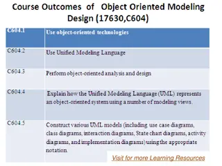
Five Key Types of UML Diagrams Activity diagrams, which show the activities involved in a process or in data processing . Use case diagrams, which show the interactions between a system and its environment. Sequence diagrams, which show interactions between actors and the system and between system components. Class diagrams, which show the object classes in the system and the associations between these classes. State diagrams, which show how the system reacts to internal and external events. Source: SE9 by Ian Sommerville Chapter 5 System modeling 7
Models of a System System modeling is the process of developing abstract models of a system, with each model presenting a different view or perspective of that system (e.g. structural, behavioral ,etc.). 1. Context models 2. Interaction models 3. Structural models 4. Behavioral models Source: SE9 by Ian Sommerville Chapter 5 System modeling 8
1. Context Models Context models are used to illustrate the operational context of a system. They show what lies outside the system boundaries. Context models simply show the other systems in the environment, not how the system being developed is used in that environment. Social and organisational concerns may affect the decision on where to position system boundaries. Source: SE9 by Ian Sommerville Chapter 5 System modeling 9
Example: The context of the MHC-PMS Source: SE9 by Ian Sommerville Chapter 5 System modeling 10
System Boundaries System boundaries are established to define what is inside and what is outside the system. They show other systems that are used or depend on the system being developed. The position of the system boundary has a profound effect on the system requirements. Defining a system boundary is a political judgment. There may be pressures to develop system boundaries that increase / decrease the influence or workload of different parts of an organization. Source: SE9 by Ian Sommerville Chapter 5 System modeling 11
Process Perspective As context models do not show the types of relationships between the systems in the environment and the system that is being specified, other models such as business process models might be used along with Context models. Process models reveal how the system being developed is used in broader business processes. UML activity diagrams may be used to define business process models. Source: SE9 by Ian Sommerville Chapter 5 System modeling 12
Example: Process Model Of Involuntary Detention Source: SE9 by Ian Sommerville Chapter 5 System modeling 13
2. Interaction Models Modeling user interaction is important as it helps to identify user requirements. Modeling system-to-system interaction highlights the communication problems that may arise. Modeling component interaction helps us understand if a proposed system structure is likely to deliver the required system performance and dependability. Use case diagrams and sequence diagrams may be used for interaction modelling. Source: SE9 by Ian Sommerville Chapter 5 System modeling 14
2.1 Interaction Modeling Using Use Case Diagrams Use cases were developed originally to support requirements elicitation and now incorporated into the UML. Each use case represents a discrete task that involves external interaction with a system. Represented diagrammatically to provide an overview of the use case and in a more detailed textual form. Actors in a use case may be people or other systems. Example: Use cases in the MHC-PMS involving the role Medical Receptionist Source: SE9 by Ian Sommerville Chapter 5 System modeling 15
2.2 Interaction Modeling Using Sequence Diagrams A sequence diagram shows the sequence of interactions that take place during a particular use case or use case instance. Sequence diagrams are used to model the interactions between the actors and the objects within a system. The objects and actors involved are listed along the top of the diagram, with a dotted line drawn vertically from these. Interactions between objects are indicated by annotated arrows Source: SE9 by Ian Sommerville Chapter 5 System modeling 16
Example: A Sequence Diagram For Viewing Patient Information Source: SE9 by Ian Sommerville Chapter 5 System modeling 17
3. Structural Models Structural models of software display the organization of a system s components and their relationships. Structural models are created when discussing and designing the system architecture. Structural models may be: Static models, which show the structure of the system design, or Dynamic models, which show the organization of the system when it is executing. UML class, component, package, and deployment diagrams may all be used when presenting architectural models. We will focus only on the use of class diagrams for modeling the static structure of the object classes in a software system. Source: SE9 by Ian Sommerville Chapter 5 System modeling 18
Classes and associations: Example of the MHC-PMS Source: SE9 by Ian Sommerville Chapter 5 System modeling 19
3.1 Class Diagrams Class diagrams are used when developing an object- oriented system model to show the classes in a system and the associations between these classes. An association is a link between classes that indicates that there is some relationship between these classes. When you are developing models during the early stages of the software engineering process, objects represent something in the real world, such as a patient, a prescription, doctor, etc. Attention! Source: SE9 by Ian Sommerville Chapter 5 System modeling 20
3.2 Generalization In object-oriented languages, such as Java, generalization is implemented using the class inheritance mechanisms built into the language. In a generalization, the attributes and operations associated with higher- level classes are also associated with the lower-level classes. The lower-level classes are subclasses inherit the attributes and operations from their super-classes. These lower-level classes then add more specific attributes and operations. Source: SE9 by Ian Sommerville Chapter 5 System modeling 21
3.2 Generalization Cont. In modeling systems, it is often useful to examine the classes in a system to see if there is scope for generalization. Why? Because, if changes are proposed, then you do not have to look at all classes in the system to see if they are affected by the change. More Examples: Source: SE9 by Ian Sommerville Chapter 5 System modeling 22
3.3 Aggregation An aggregation model shows classes that are composed of other classes (i.e. part-of relationship ) Source: SE9 by Ian Sommerville Chapter 5 System modeling 23
4. Behavioral Models Behavioral models are models of the dynamic behavior of a system as it is executing. They show what happens or what is supposed to happen when a system responds to a stimulus from its environment. You can think of these stimuli as being of two types: Data Some data arrives that has to be processed by the system. Events Some event happens that triggers system processing. Events may have associated data, although this is not always the case. Source: SE9 by Ian Sommerville Chapter 5 System modeling 24
4.1 Data-driven Modeling Many business systems are data-processing systems that are primarily driven by data. They are controlled by the data input to the system, with relatively little external event processing. Data-driven models show the sequence of actions involved in processing input data and generating an associated output. They are particularly useful during the analysis of requirements as they can be used to show end-to-end processing in a system. Source: SE9 by Ian Sommerville Chapter 5 System modeling 25
Example: An activity model of the insulin pump s operation Source: SE9 by Ian Sommerville Chapter 5 System modeling 26
Example: Order processing Source: SE9 by Ian Sommerville Chapter 5 System modeling 27
4.2 Event-driven Modeling Real-time systems are often event-driven, with minimal data processing. Event-driven modeling shows how a system responds to external and internal events. It is based on the assumption that a system has a finite number of states and that events (stimuli) may cause a transition from one state to another. Source: SE9 by Ian Sommerville Chapter 5 System modeling 28
State Machine Models These model the behaviour of the system in response to external and internal events. They show the system s responses to stimuli so are often used for modelling real-time systems. State machine models show system states as nodes and events as arcs between these nodes. When an event occurs, the system moves from one state to another. State-charts are an integral part of the UML and are used to represent state machine models. Source: SE9 by Ian Sommerville Chapter 5 System modeling 29
Example: State diagram of a microwave oven Source: SE9 by Ian Sommerville Chapter 5 System modeling 30
States and stimuli for the microwave oven (a) State Waiting Half power The oven power is set to 300 watts. The display shows Half power . Full power The oven power is set to 600 watts. The display shows Full power . Set time The cooking time is set to the user s input value. The display shows the cooking time selected and is updated as the time is set. Disabled Oven operation is disabled for safety. Interior oven light is on. Display shows Not ready . Enabled Oven operation is enabled. Interior oven light is off. Display shows Ready to cook . Operation Oven in operation. Interior oven light is on. Display shows the timer countdown. On completion of cooking, the buzzer is sounded for five seconds. Oven light is on. Display shows Cooking complete while buzzer is sounding. Description The oven is waiting for input. The display shows the current time. Source: SE9 by Ian Sommerville Chapter 5 System modeling 31
States and stimuli for the microwave oven (b) Stimulus Half power Description The user has pressed the half-power button. Full power The user has pressed the full-power button. Timer The user has pressed one of the timer buttons. Number The user has pressed a numeric key. Door open The oven door switch is not closed. Door closed The oven door switch is closed. Start The user has pressed the Start button. Cancel The user has pressed the Cancel button. Source: SE9 by Ian Sommerville Chapter 5 System modeling 32
System modeling Context models Interaction models Structural models Behavioral models Model-driven engineering (MDE) Source: SE9 by Ian Sommerville Chapter 5 System modeling 33
Model-driven Engineering (MDE) MDE is an approach to software development where models rather than programs are the principal outputs of the development process. The programs that execute on a hardware/software platform are then generated automatically from these models. Source: SE9 by Ian Sommerville Chapter 5 System modeling 34
Questions? Source: SE9 by Ian Sommerville 35


")
")

")