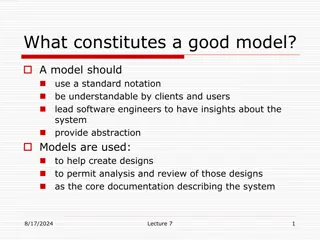
Conceptual and Requirement Modelling Using UML

undefined
Conceptual and Requirement Modelling
using Unified Modelling Language (UML)
- with solutions
Erik
 
Perjons
DSV, Stockholm University
perjons@dsv.su.se
Enterprise 
and 
System
 
Models
Real 
World and
 
Models
I
n
t
e
r
a
c
t
i
o
n
b
e
t
w
e
e
n
 
s
o
f
t
w
a
r
e
o
b
j
e
k
t
s
(in 
UML
 
Sequence
diagram)
T
h
e
 
r
e
a
l
 
w
o
r
l
d
G
r
a
p
h
i
c
a
l
 
m
o
d
e
l
s
/
d
i
a
g
r
a
m
D
o
m
a
i
n
 
m
o
d
e
l
o
f
 
b
u
s
i
n
e
s
s
c
o
n
c
e
p
t
s
(in 
UML
 
Class
di
ag
ram)
S
y
s
t
e
m
 
m
o
d
e
l
 
o
f
s
o
f
t
w
a
r
e
 
o
b
j
e
c
t
s
(
i
n
 
U
M
L
 
C
l
a
s
s
di
ag
ram)


H
u
m
a
n
 
i
n
t
e
r
a
c
t
i
o
n
 
w
i
t
h
s
o
f
t
w
a
r
e
 
s
y
s
t
a
m
(in 
UML Use
 
cases)
B
u
s
i
n
e
s
s
 
p
r
o
c
e
s
s
 
m
o
d
e
l
of business
 
activities
(in 
UML 
Activity
 
diagram)
Enterprise 
and 
System Models
System
models
E
n
t
erprise
models/
Business
models
Why 
e
nterprise
 
model
s?
Enterprise 
models are useful
 
for:
analy
z
ing 
business processes and business concepts
designing 
more
 
efficient business processes
designing a common conceptual base for the organization
providing requirements on software system solutions
Why s
ystem
 
model
s?
System models 
are useful tools
 
for:
analysing software system
s
designing 
software system
s that are align with the business
processes
designing software systems using a model driven approach
Static 
and 
Dynamic
 
Models
Dynamic/Behavioural 
models
-
represent
 
dynamic aspects of 
the real
 
world/system
-
more precisely: how does objects and their relationships
 
change
-
answer the questions: “How does the things
 
change”
Static/Structural
 
models
-
represent
 static aspects of the real
 
world/system
-
more precisely: 
which 
objects exists and their
 
relationships
-
answer the question: “What things
 
exist?
Modelling
 
Language
 
         
Static/Structural
 
model
r
ep
r
ese
n
t
ed
by
Dynamic/Behavoural
 
model
us
i
ng
us
i
n
g
consists
 
of
A
b
s
t
r
a
c
t
 
S
y
n
t
a
x
 
d
e
f
i
n
e
 
t
h
e
 
l
a
n
g
u
a
g
e
s
c
e
n
t
r
a
l
 
c
o
n
c
e
p
t
,
u
s
u
a
l
l
y
 
i
n
 
f
o
r
m
 
o
f
 
a
m
e
t
a
m
o
d
e
l
C
o
n
c
r
e
t
e
 
S
y
n
t
a
x
 
d
e
s
c
r
i
b
e
 
w
h
i
c
h
s
y
m
b
o
l
s
 
t
h
e
 
l
a
n
g
u
a
g
e
c
o
n
s
i
s
t
s
 
o
f
 
a
n
d
 
h
o
w
t
h
e
y
 
l
o
o
k
 
l
i
k
e
,
 
c
a
l
l
e
d
t
h
e
 
n
o
t
a
t
i
o
n
UML
Unified 
Modelling Language (UML) 
is 
a 
general-purpose 
modelling
language/technique which is designed to provide 
a 
standard 
way 
to
visualize the design 
of a 
software 
system - 
but the language 
can also
be 
used for enterprise
 
modelling
Maintained by 
Object Management Group 
(OMG)
UML
 
diagrams
Diagrams
 
(13)
Structure 
diagram
 
(6)
Behaviour diagram
 
(7)
Activity
 
diagram
Use
 
Case
Class
 
diagram
UML 2.0 has 13 
diagram 
types, which 
each 
provide 
a certain
focus/perspective 
on a 
model. 
According 
to 
UML 
there is 
one model of
a system, and 
the 
different 
diagrams provide different perspectives
 
of
that
 
model
Sequence diagram
State machine diag.
UML Class Diagram
Real 
World and
 
Models
I
n
t
e
r
a
c
t
i
o
n
b
e
t
w
e
e
n
 
s
o
f
t
w
a
r
e
o
b
j
e
k
t
s
(in 
UML
 
Sequence
diagram)
T
h
e
 
r
e
a
l
 
w
o
r
l
d
G
r
a
p
h
i
c
a
l
 
m
o
d
e
l
s
/
d
i
a
g
r
a
m
D
o
m
a
i
n
 
m
o
d
e
l
o
f
 
b
u
s
i
n
e
s
s
c
o
n
c
e
p
t
s
(in 
UML
 
Class
di
ag
ram)
S
y
s
t
e
m
 
m
o
d
e
l
 
o
f
s
o
f
t
w
a
r
e
 
o
b
j
e
c
t
s
(
i
n
 
U
M
L
 
C
l
a
s
s
di
ag
ram)


H
u
m
a
n
 
i
n
t
e
r
a
c
t
i
o
n
 
w
i
t
h
s
o
f
t
w
a
r
e
 
s
y
s
t
a
m
(in 
UML Use
 
cases)
B
u
s
i
n
e
s
s
 
p
r
o
c
e
s
s
 
m
o
d
e
l
of business
 
activities
(in 
UML 
Activity
 
diagram)
A class is shown as a rectangle with three compartments:
name of the class (use a noun in singular, first letter capital)
attribute(s) (use a noun in singular for each atttribute, first
letter lower case)
operation(s) (use a verb, first letter lower case)
Class
Student
studentNo
name
mobileNo
registerForCourse()
N
a
m
e
A
t
t
r
i
b
u
t
e
O
p
e
r
a
t
i
o
n
The class can be shown in three different variants
We will use the variant in the middle showing the name of the
class and the attributes
Class
Student
studentNo
name
mobileNo
registerForCourse()
Student
studentNo
name
mobileNo
Student
A class groups a set of things with common properties or
characteristics
Class
Student
studentNo
name
mobileNo
A class groups a set of things with common properties or
characteristics
An attribute is a descriptive property or characteristic of the
class
Class
Student
studentNo
name
mobileNo
A class groups a set of things with common properties or
characteristics
An attribute is a descriptive property or characteristic of the
class
Class
Student
studentNo
name
mobileNo
Association is shown as a line between classes
In order to support interpretation of the association, it should be
given a name – preferably in form of a verb or verb phrase – and it
should also be visualized in which direction the name should be
read
Association
Student
studentNo
name
mobileNo
Course
courseNo
courseName
registered at
A
s
s
o
c
i
a
t
i
o
n
N
a
m
e
 
o
f
 
t
h
e
 
a
s
s
o
c
i
a
t
i
o
n
Association has two directions – one from Student to Course
and one from Course to Student
Association
Student
studentNo
name
mobileNo
Course
courseNo
courseName
registered at
Only the name of the association in one direction is usually
shown, but there is possible to use names in both direction
Association
Student
studentNo
name
mobileNo
Course
courseNo
courseName
registered at
has registered
Association shows the roles the objects of the classes can plays
towards each other
There is a role in each direction of the association:
Student plays the role of being registered at course(s)
Course plays the role of having registered student(s)
Association
Student
studentNo
name
mobileNo
Course
courseNo
courseName
registered at
It is possible to specify that an association only has one
direction by introducing a navigation arrow
Association
Student
studentNo
name
mobileNo
Course
courseNo
courseName
registered at
A
s
s
o
c
i
a
t
i
o
n
i
n
 
f
o
r
m
 
o
f
 
a
N
a
v
i
g
a
t
i
o
n
a
r
r
o
w
Modelling Class and Objects
Instantiation
Class and Association Structure
A class and association structure can be seen an
information structure
, constraining what objects and links
are possible to create/instantiate
Student
studentNo
name
mobileNo
Course
CourseNo
CourseName
registers for
C
l
a
s
s
A
s
s
o
c
i
a
t
i
o
n
C
l
a
s
s
Creating Object and Link structures
Class and
association
structures
Object and link
structures
registers for
Object and Link structures
Object and link structures are usually not modelled, but
could be:
Elsa Falk: Student
studentNo=100123
Name=Elsa Falk
mobileNo=070-112233
 SUPCOM:Course
CourseNo=14
CourseName=SUPCOM
registers for
O
b
j
e
c
t
L
i
n
k
O
b
j
e
c
t
Multiplicity describes how many objects (minimum and
maximum) of a class that can be linked to objects of an other
class – in both directions of the association
M
inimum can be 0 (”cero”) eller 1 (”one”)
Maximum can be 1 (”one”) or * (”many”)
Multiplicity
Customer
customerNo
name
emailAddress
placed
0..*
1..1
Order
orderNo
totalSum
Multiplicity describes how many objects (minimum and
maximum) of a class that can be linked to objects of an other
class – in both directions of the association
M
inimum can be 0 (”cero”) eller 1 (”one”)
Maximum can be 1 (”one”) or * (”many”)
Multiplicity
Customer
customerNo
name
emailAddress
placed
0..*
1..1
M
u
l
t
i
p
l
i
c
i
t
y
w
i
t
h
 
m
i
n
 
a
n
d
m
a
x
 
v
a
l
u
e
Order
orderNo
totalSum
C
u
s
t
o
m
e
r
customerNo
name
eMailAddress
O
r
d
e
r
orderNo
totalSum
1
.
.
1
0
.
.
*
:
C
u
s
t
o
m
e
r
:
O
r
d
e
r
Multiplicitet
:
C
u
s
t
o
m
e
r
:
O
r
d
e
r
customerNo=223344
name=Anna Lönn
eMailAddress=lonn@hotmail
customerNo=112233
name:=Zlatan”
eMailAddress=z@hotmail
orderNo=9945361
totalSum=5124SEK
orderNo=9945362
totalSum=402SEK
placed
L
i
n
k
O
b
j
e
c
t
C
l
a
s
s
A
s
s
o
c
i
a
t
i
o
n
Multiplicy in the direction from Customer to Order: 
An object of a
class Customer can minimum be linked to 0 and maximum to many
Multiplicy in the direction from Order to Customer: 
An object of a
class Customer can minimum be linked to 1 and maximum to 1,
that is, exactly one
Multiplicity
Customer
customerNo
name
emailAddress
placed
0..*
1..1
Order
orderNo
totalSum
A guideline to use for helping you deciding multiplicity:
Use the phase: ”
One object of
 Customer 
is linked to minimum
{zero or one} 
and
 
maximum
 {one or many} 
object(s) of
Order”, and (in the other direction): ”
One object of
 Order 
is
linked to minimum
 {zero or one} 
and
 
maximum
 {one or
many} 
object(s) of 
Customer”
Multiplicity
Customer
customerNo
name
emailAddress
Order
orderNo
totalSum
placed
0..*
1..1
Multiplicity Exercise
C
a
r
licenceNo
O
w
n
e
r
nationalIdNo
1
.
.
1
1
.
.
*
Your task: 
Find the violation of multiplicity rules and correct
the multiplicity
:
C
a
r
licenceNo=UML123
:
O
w
n
e
r
nationalIdNo =“771134”
:
O
w
n
e
r
nationalIdNo=“871211”
:
O
w
n
e
r
nationalIdNo=891223”
:
C
a
r
licenceNo=OMG234
:
C
a
r
licenceNo=MDA345
Multiplicity Exercise
C
a
r
licenceNo
O
w
n
e
r
nationalIdNo
0
.
.
*
0
.
.
*
Your task: 
Find the violation of multiplicity rules and correct
the multiplicity
:
C
a
r
licenceNo=UML123
:
O
w
n
e
r
nationalIdNo =“771134”
:
O
w
n
e
r
nationalIdNo=“871211”
:
O
w
n
e
r
nationalIdNo=891223”
:
C
a
r
licenceNo=OMG234
:
C
a
r
licenceNo=MDA345
Commonly,  multiplicity described business rules in the
organization (for example, a order must be placed by exactly
one customer)
Multiplicity
44
T
e
a
c
h
e
r
name
address
teacherID
S
t
u
d
e
n
t
name
address
studentNumber
T
e
a
c
h
e
r
teacherID
S
t
u
d
e
n
t
studentNumber
P
e
r
s
o
n
name
address
Modelling Generalization in UML
T
e
a
c
h
e
r
teacherID
S
t
u
d
e
n
t
studentNumber
P
e
r
s
o
n
name
address
Modelling Generalization in UML
C
o
m
p
u
t
e
r
T
e
a
c
h
e
r
M
a
t
h
T
e
a
c
h
e
r
Modelling generalization in UML
P
e
r
s
o
n
T
e
a
c
h
e
r
S
t
u
d
e
n
t
S
u
p
e
r
c
l
a
s
s
S
u
b
c
l
a
s
s
S
u
b
c
l
a
s
s
Real World
The Model World
Generalization
Generalizering are
grouping of classes,
where classes totally
include others
The opposite to
generalization is
specialization
Person is a generalization of Woman and Student
Woman and Student are specializations of Person
Domain description
This is a domain description of small university library in Sweden
For each borrower, the library needs to have information of 
national ID Number (called personal number in Sweden),
name, address and library card number
For each employed librarian, the library needs to have 
national ID Number (called personal number in Sweden),
name, address, library card number and employee number
A borrower can borrow books. For each loan, the library needs to know which book copy the loan concerns, date of
the loan, the date when the copy needs be returned. For each loan, a librarian needs to confirm the loan
For each book title the library needs to have information about: author, title, publisher, ISBN, and what category it
belongs to. Regarding copies of books, the library needs to have information of the date of purchase of the copy and
which copy number the book has (this number is provided by the library directly after purchase). This copy number
is used to identify individual copies of a book, because popular books have several copies
B
o
r
r
o
w
e
r
L
i
b
r
a
r
i
a
n
P
e
r
s
o
n
name
address
nationalIDNumber
libraryCardNo
employeeNo
B
o
o
k
T
i
t
l
e
title
author
publisher
isbn
category
B
o
o
k
C
o
p
y
copyNo
purchaseDate
is item of
B
o
o
k
L
o
a
n
made by
confirmed_by
concerns
loanDate
plannedReturnDate
returned (Y/N)
0..*
0..*
0..*
1..*
1
.
.
1
1
.
.
1
1
.
.
1
1
.
.
1
Requirement Engineering and Use Cases
Requirement
Requirement
 is a desirable
property/feature/attribute/quality/capacity of a system
Requirement Engineering
Requirement Engineering 
is the process of gathering,
defining, organizing, prioritizing, documenting, quality
assuring and maintaining requirements
Requirement
Requirements can be categorized into:
Functional requirements
Non-functional requirements
Functional Requirement
Functional requirements 
– are functions that a system should
perform.
A functional requirement - is 
something that a system should do
based on an active action from a user
Functional Requirement
Examples of functional requirements:
The sytem should be able to register an order
The sytem should be able to register an new customer
The system should be able to find a customer when searching after a registered
customer in the system by using customer id or customer name
Non-functional Requirement
Non-functional requirements 
– are requirements of 
how
a system should perform the functions of the system
Non-functional requirement are related to qualities of the
system, such as performance, reliability, usability, security,
platform constraints
Non-functional Requirement
Examples of non-functional requirements:
The system must be able to handle 100 orders in parallel
The system must be able to integrate with systems in a Microsoft
platform
Requirement Specification
Requirement specification 
is a document specifying the
requirements of a system.
The core of the requirement specification is
, therefore, to
specify the 
functional and non-functional requirements
Requirement Specification
Usually the 
requirement specification also describe the
context of the requirements
, such as which business
problems should be addressed by the system and/or the
business processes that should be supported by the system
Why Requirement Engineering?
The 
major reason for failure in system development is
shortcoming in requirement engineering
, such as:
no requirements have been gathered at all
not all users (or other stakeholders) have been involved in the
requirement gathering
the requirements are vaguely stated
users do not know what they want before they use the system in
actual business process instances
Why Requirement Engineering?
The requirements are
 central in the development of a
system and are often the things that drive the
development process
Why Requirement Engineering?
However, the traditional way of handling requirements –
using the 
waterfall principle 
- has been heavily critizised
Waterfall Principle
Waterfall principle 
is based on
the idea that all requirements
should be defined before the
overall design of the system is
started.
Requirement
Design
Implementation
Test & Deploy
Waterfall Principle Evaluated
Drawback of Waterfall principle:
many systems developed using the waterfall principle are not
successful, mainly due to limited customer feedback during
the project
problem to handle changed requirments during development
often results in extensive production of documents that are
not used (i.e. easily become bureaucratic)
Iteration Principle
Iteration principle 
is based on the idea that a system should be
developed in a set of mini project. Each miniproject, called an
iteration, involve a limited set of requirements, which are designed,
implemented and deployed to receive early user feedback
Agile Methods
Agile methods 
are a group of 
iterative
 system development
methods that share a set of 
values 
and
 principles 
that should
govern the system development – presented in the Agile
Manifesto
Agiles methods also provide a set of
 practices 
to use for
supporting the values and principles, for example pair
programming and time boxing
Most well-known agile methods are: 
eXtreme Programming
(XP), Scrum, Crystal, Lean Software Development
The requirement specification can consist of only text or both
text and models:
Functional requirements can be listed in form of text or as a
combination of diagram and text (e.g. UML Use Case
Diagram and Use Case Description)
The context of the requitements can be be described in form
of text and/or models, e.g. business process models
Requirement Specification and Models
68
UML Use Case
UML Use Case Diagram
R
e
g
i
s
t
r
e
r
f
o
r
 
c
o
u
r
s
e
R
e
g
i
s
t
e
r
f
o
r
 
e
x
a
m
UML Use Case Diagram
R
e
g
i
s
t
r
e
r
f
o
r
 
c
o
u
r
s
e
R
e
g
i
s
t
e
r
f
o
r
 
e
x
a
m
A
c
t
o
r
U
s
e
 
C
a
s
e
A
s
s
o
c
i
a
t
i
o
n
Use Case Description
Use case description
describe the interaction
between a user and the
system
The look of the use case
description is not specified in
UML
U
s
e
 
c
a
s
e
:
 
 
R
e
g
i
s
t
r
e
r
 
f
o
r
 
c
o
u
r
s
e
A
c
t
o
r
:


S
t
u
d
e
n
t
Goal:
 
       Student shall be registered for the
 
       course
Main scenario:    1) Student wants to see available
 
      courses
 
      2) System presents the cources
 
      3) Student chooses a course
 
      4) Systemet confirms registration of
 
      the chosen course
 
Use Case Model
Use case model – 
consists of 
Use case diagram 
and 
Use case
descriptions
Guidelines for the Use Case Model
Guideline: 
Create
 
one Use case description for each use case in
the Use case diagram
Guideline: 
Use the same name of the use case in the descrption
as in the use case diagram
More about Use Case Description
Guideline: 
The m
ain scenario
shall be divided into a set of
steps, which each need to:
start with who is carrying
out the step (the actor or
the system)
be simple and precise
statements of what are
communicated between
the actor and the system
U
s
e
 
c
a
s
e
:
 
 
R
e
g
i
s
t
r
e
r
 
f
o
r
 
c
o
u
r
s
e
A
c
t
o
r
:


S
t
u
d
e
n
t
Goal:
 
       Student shall be registered for the
 
       course
Main scenario:    1) Student wants to see available
 
      courses
 
      2) System presents the cources
 
      3) Student chooses a course
 
      4) Systemet confirms registration of
 
      the chosen course
 
Zoo International is a company with eight zoos in different European cities. Zoo International has specified an introduction
process that all zoos should follow. In order to support the introduction process, Zoo International aims to introduce an
information system (IS) supporting the process. 
As a first step, requirements on the IS have been gathered from different stakeholders. Three of the requirements are as follows:
 When an animal arrive at a zoo (which is part of Zoo International) the animal needs to be registered in the IS by one of
the 
zoo adminstrators
. The following information must then be registered in the information system by the administator:
date of registration, name of the animal, spieces, gender, year of birth
For each animal arriving at the zoo, one of the zoo veterinarian needs to document information in the IS about the medical
status of the animal after carrying out a medical investigation
For each animal arriving at the zoo, one of the animal keepers needs to document the result of the meeting between the
arrived animal and its
 ”cage colleagues”
Domain Description
Register animal
Document medical status
Document result from meeting
with ”cage colleagues”
Veterinarian
Animal keeper
Administrator
Register animal
Document medical status
Document result from meeting
with ”cage colleagues”
Veterinarian
Animal keeper
Administrator
U
s
e
 
c
a
s
e
:
 
 
R
e
g
i
s
t
r
e
r
 
a
n
i
m
a
l
A
c
t
o
r
:


A
d
m
i
n
i
s
t
r
a
t
o
r
Goal:
 
       Animal must be registered at the zoo
Main scenario: 1) Administrator asks for register arrived animal
 
          2) System presents registration form
 
          3) Administrator registers the animal with required info
                             (
date of registration, name of the animal, spieces, gender, year of birth)
 
          4) Systemet confirms registration 
 
Register animal
Administrator
U
s
e
 
c
a
s
e
:
 
 
R
e
g
i
s
t
r
e
r
 
a
n
i
m
a
l
A
c
t
o
r
:


A
d
m
i
n
i
s
t
r
a
t
o
r
Goal:
 
       Animal must be registered at the zoo
Main scenario: 1) Administrator asks for register arrived animal
 
      2) System presents registration form
 
      3) Administrator registers the animal wihj required info
                             (
date of registration, name of the animal, spieces, gender, year of birth)
 
      4) Systemet confirms registration 
 
U
s
e
 
c
a
s
e
:
 
 
D
o
c
u
m
e
n
t
 
m
e
d
i
c
a
l
 
s
t
a
t
u
s
A
c
t
o
r
:


V
e
t
e
r
i
n
a
r
i
a
n
Goal:
 
       Medical status of animal must be documented
Main scenario: 1) Veterinarian asks for document the medical status of an animal
 
      2) System presents medical status form
 
      3) Veterinarian documents 
medical staus 
and
 date for medical
investigation 
 
      4) Systemet confirms documentation
 
U
s
e
 
c
a
s
e
:
 
 
D
o
c
u
m
e
n
t
 
r
e
s
u
l
t
 
f
r
o
m
 
m
e
e
t
i
n
g
 
w
i
t
h
 
c
a
g
e
 
c
o
l
l
e
a
g
u
e
s
A
c
t
o
r
:


A
n
i
m
a
l
 
k
e
e
p
e
r
Goal:
 
       Result from animal’s meeting 
with ”cage colleagues” must 
be
documented
Main scenario: 1) Animal keeper asks for document animal meeting with 
”cage colleagues” 
 
      2) System presents form for document meeting
 
      3) Animal keeper documents 
result from meeting 
and 
date for meeting
 
      4) Systemet confirms documentation
 
Other types of UML diagram
Real 
World and
 
Models
I
n
t
e
r
a
c
t
i
o
n
b
e
t
w
e
e
n
 
s
o
f
t
w
a
r
e
o
b
j
e
k
t
s
(in 
UML
 
Sequence
diagram)
T
h
e
 
r
e
a
l
 
w
o
r
l
d
G
r
a
p
h
i
c
a
l
 
m
o
d
e
l
s
/
d
i
a
g
r
a
m
D
o
m
a
i
n
 
m
o
d
e
l
o
f
 
b
u
s
i
n
e
s
s
c
o
n
c
e
p
t
s
(in 
UML
 
Class
di
ag
ram)
S
y
s
t
e
m
 
m
o
d
e
l
 
o
f
s
o
f
t
w
a
r
e
 
o
b
j
e
c
t
s
(
i
n
 
U
M
L
 
C
l
a
s
s
di
ag
ram)


H
u
m
a
n
 
i
n
t
e
r
a
c
t
i
o
n
 
w
i
t
h
s
o
f
t
w
a
r
e
 
s
y
s
t
a
m
(in 
UML Use
 
cases)
B
u
s
i
n
e
s
s
 
p
r
o
c
e
s
s
 
m
o
d
e
l
of business
 
activities
(in 
UML 
Activity
 
diagram)
Activity diagram
Real 
World and
 
Models
I
n
t
e
r
a
c
t
i
o
n
b
e
t
w
e
e
n
 
s
o
f
t
w
a
r
e
o
b
j
e
k
t
s
(in 
UML
 
Sequence
diagram)
T
h
e
 
r
e
a
l
 
w
o
r
l
d
G
r
a
p
h
i
c
a
l
 
m
o
d
e
l
s
/
d
i
a
g
r
a
m
D
o
m
a
i
n
 
m
o
d
e
l
o
f
 
b
u
s
i
n
e
s
s
c
o
n
c
e
p
t
s
(in 
UML
 
Class
di
ag
ram)
S
y
s
t
e
m
 
m
o
d
e
l
 
o
f
s
o
f
t
w
a
r
e
 
o
b
j
e
c
t
s
(
i
n
 
U
M
L
 
C
l
a
s
s
di
ag
ram)


H
u
m
a
n
 
i
n
t
e
r
a
c
t
i
o
n
 
w
i
t
h
s
o
f
t
w
a
r
e
 
s
y
s
t
a
m
(in 
UML Use
 
cases)
B
u
s
i
n
e
s
s
 
p
r
o
c
e
s
s
 
m
o
d
e
l
of business
 
activities
(in 
UML 
Activity
 
diagram)
Sequence diagram
State machine diagram
Information standard in healthcare
Healthcare
standard
CONTSYS
Healthcare
standard
HL7 RIM
OMG’s Model Driven Architecture
Real 
World and
 
Models
I
n
t
e
r
a
c
t
i
o
n
b
e
t
w
e
e
n
 
s
o
f
t
w
a
r
e
o
b
j
e
k
t
s
(in 
UML
 
Sequence
diagram)
T
h
e
 
r
e
a
l
 
w
o
r
l
d
G
r
a
p
h
i
c
a
l
 
m
o
d
e
l
s
/
d
i
a
g
r
a
m
D
o
m
a
i
n
 
m
o
d
e
l
o
f
 
b
u
s
i
n
e
s
s
c
o
n
c
e
p
t
s
(in 
UML
 
Class
di
ag
ram)
S
y
s
t
e
m
 
m
o
d
e
l
 
o
f
s
o
f
t
w
a
r
e
 
o
b
j
e
c
t
s
(
i
n
 
U
M
L
 
C
l
a
s
s
di
ag
ram)


H
u
m
a
n
 
i
n
t
e
r
a
c
t
i
o
n
 
w
i
t
h
s
o
f
t
w
a
r
e
 
s
y
s
t
a
m
(in 
UML Use
 
cases)
B
u
s
i
n
e
s
s
 
p
r
o
c
e
s
s
 
m
o
d
e
l
of business
 
activities
(in 
UML 
Activity
 
diagram)
Model Driven Architecture


Computation
Independent Model (CIM)
Platform Independent Model (PIM)
Platform Dependent Model (PSM)
Code
Model Driven Architecture


Computation
Independent Model (CIM)
Platform Independent Model (PIM)
Platform Dependent Model (PSM)
Code
transformation
transformation
transformation
Slide Note
Embed
Share

Enterprise and system models play a crucial role in the business world. This collection of images showcases various aspects of conceptual and requirement modelling using Unified Modelling Language (UML). From business process models to human interactions with software systems, these visual representations provide insights into real-world scenarios and system models. Dive into the world of UML to gain a better understanding of how businesses model their activities and concepts.

  • UML
  • Conceptual Modelling
  • Requirement Modelling
  • Business Process
  • System Models

Uploaded on Aug 17, 2024 | 1 Views


Download Presentation

Please find below an Image/Link to download the presentation.

The content on the website is provided AS IS for your information and personal use only. It may not be sold, licensed, or shared on other websites without obtaining consent from the author. Download presentation by click this link. If you encounter any issues during the download, it is possible that the publisher has removed the file from their server.

E N D

Presentation Transcript


  1. Conceptual and Requirement Modelling using Unified Modelling Language (UML) - with solutions Erik Perjons DSV, Stockholm University perjons@dsv.su.se

  2. Enterprise and System Models

  3. Real World and Models Business process model of business activities (in UML Activitydiagram) Domainmodel ofbusiness concepts (in UML Class diagram) Human interactionwith softwaresystam (in UML Use cases) Interaction between software objekts (in UML Sequence diagram) System model of softwareobjects (in UML Class diagram) The realworld Graphical models/diagram

  4. Real World and Models Business process model of business activities (in UML Activitydiagram) Domainmodel ofbusiness concepts (in UML Class diagram) Human interactionwith softwaresystam (in UML Use cases) Interaction between software objekts (in UML Sequence diagram) System model of softwareobjects (in UML Class diagram) The realworld Graphical models/diagram

  5. Real World and Models Business process model of business activities (in UML Activitydiagram) Domainmodel ofbusiness concepts (in UML Class diagram) Human interactionwith softwaresystam (in UML Use cases) Interaction between software objekts (in UML Sequence diagram) System model of softwareobjects (in UML Class diagram) The realworld Graphical models/diagram

  6. Real World and Models Business process model of business activities (in UML Activitydiagram) Domainmodel ofbusiness concepts (in UML Class diagram) Human interactionwith softwaresystam (in UML Use cases) Interaction between software objekts (in UML Sequence diagram) System model of softwareobjects (in UML Class diagram) The realworld Graphical models/diagram

  7. Real World and Models Business process model of business activities (in UML Activitydiagram) Domainmodel ofbusiness concepts (in UML Class diagram) Human interactionwith softwaresystam (in UML Use cases) Interaction between software objekts (in UML Sequence diagram) System model of softwareobjects (in UML Class diagram) The realworld Graphical models/diagram

  8. Real World and Models Business process model of business activities (in UML Activitydiagram) Domainmodel ofbusiness concepts (in UML Class diagram) Human interactionwith softwaresystam (in UML Use cases) Interaction between software objekts (in UML Sequence diagram) System model of softwareobjects (in UML Class diagram) The realworld Graphical models/diagram

  9. Real World and Models Business process model of business activities (in UML Activitydiagram) Domainmodel ofbusiness concepts (in UML Class diagram) Human interactionwith softwaresystam (in UML Use cases) Interaction between software objekts (in UML Sequence diagram) System model of softwareobjects (in UML Class diagram) The realworld Graphical models/diagram

  10. Real World and Models Business process model of business activities (in UML Activitydiagram) Domainmodel ofbusiness concepts (in UML Class diagram) Human interactionwith softwaresystam (in UML Use cases) Interaction between software objekts (in UML Sequence diagram) System model of softwareobjects (in UML Class diagram) The realworld Graphical models/diagram

  11. Real World and Models Business process model of business activities (in UML Activitydiagram) Domainmodel ofbusiness concepts (in UML Class diagram) Human interactionwith softwaresystam (in UML Use cases) Interaction between software objekts (in UML Sequence diagram) System model of softwareobjects (in UML Class diagram) The realworld Graphical models/diagram

  12. Enterprise and System Models Enterprise models/ Business models System models

  13. Why enterprise models? Enterprise models are useful for: analyzing business processes and business concepts designing more efficient business processes designing a common conceptual base for the organization providing requirements on software system solutions

  14. Why system models? System models are useful tools for: analysing software systems designing software systems that are align with the business processes designing software systems using a model driven approach

  15. Static and Dynamic Models Static/Structuralmodels - represent static aspects of the real world/system - more precisely: which objects exists and their relationships - answer the question: What things exist? Dynamic/Behavioural models - represent dynamic aspects of the real world/system - more precisely: how does objects and their relationships change - answer the questions: How does the things change

  16. Modelling Language Static/Structural model Abstract Syntax define thelanguage s central concept, usually in form of a metamodel using Concrete Syntax describe which symbols thelanguage consists of and how they looklike, called the notation represented by consistsof using Dynamic/Behavouralmodel

  17. UML Unified Modelling Language (UML) is a general-purpose modelling language/technique which is designed to provide a standard way to visualize the design of a software system - but the language can also be used for enterprise modelling Maintained by Object Management Group (OMG)

  18. UML diagrams UML 2.0 has 13 diagram types, which each provide a certain focus/perspective on a model. According to UML there is one model of a system, and the different diagrams provide different perspectives of that model Class diagram Structure diagram(6) Diagrams(13) Activity diagram Use Case Sequence diagram State machine diag. Behaviour diagram(7)

  19. UML Class Diagram

  20. Real World and Models Business process model of business activities (in UML Activitydiagram) Domainmodel ofbusiness concepts (in UML Class diagram) Human interactionwith softwaresystam (in UML Use cases) Interaction between software objekts (in UML Sequence diagram) System model of softwareobjects (in UML Class diagram) The realworld Graphical models/diagram

  21. Class A class is shown as a rectangle with three compartments: name of the class (use a noun in singular, first letter capital) attribute(s) (use a noun in singular for each atttribute, first letter lower case) operation(s) (use a verb, first letter lower case) Student Name studentNo name mobileNo Attribute registerForCourse() Operation

  22. Class The class can be shown in three different variants We will use the variant in the middle showing the name of the class and the attributes Student Student Student studentNo name mobileNo studentNo name mobileNo registerForCourse()

  23. Class A class groups a set of things with common properties or characteristics Student studentNo name mobileNo

  24. Class A class groups a set of things with common properties or characteristics An attribute is a descriptive property or characteristic of the class Student studentNo name mobileNo

  25. Class A class groups a set of things with common properties or characteristics An attribute is a descriptive property or characteristic of the class Student studentNo name mobileNo

  26. Association Association is shown as a line between classes In order to support interpretation of the association, it should be given a name preferably in form of a verb or verb phrase and it should also be visualized in which direction the name should be read Name of the association Student Course registered at studentNo name mobileNo courseNo courseName Association

  27. Association Association has two directions one from Student to Course and one from Course to Student Student Course registered at studentNo name mobileNo courseNo courseName

  28. Association Only the name of the association in one direction is usually shown, but there is possible to use names in both direction Student Course registered at studentNo name mobileNo courseNo courseName has registered

  29. Association Association shows the roles the objects of the classes can plays towards each other There is a role in each direction of the association: Student plays the role of being registered at course(s) Course plays the role of having registered student(s) Student Course registered at studentNo name mobileNo courseNo courseName

  30. Association It is possible to specify that an association only has one direction by introducing a navigation arrow Student Course registered at studentNo name mobileNo courseNo courseName Association in form of a Navigation arrow

  31. Modelling Class and Objects Instantiation

  32. Class and Association Structure A class and association structure can be seen an information structure, constraining what objects and links are possible to create/instantiate Course Student CourseNo CourseName registers for studentNo name mobileNo Association Class Class

  33. Creating Object and Link structures Class and association structures Object and link structures registers for

  34. Object and Link structures Object and link structures are usually not modelled, but could be: SUPCOM:Course Elsa Falk: Student CourseNo=14 CourseName=SUPCOM registers for studentNo=100123 Name=Elsa Falk mobileNo=070-112233 Link Object Object

  35. Multiplicity Multiplicity describes how many objects (minimum and maximum) of a class that can be linked to objects of an other class in both directions of the association Minimum can be 0 ( cero ) eller 1 ( one ) Maximum can be 1 ( one ) or * ( many ) Customer Order 1..1 0..* customerNo name emailAddress orderNo totalSum placed

  36. Multiplicity Multiplicity describes how many objects (minimum and maximum) of a class that can be linked to objects of an other class in both directions of the association Minimum can be 0 ( cero ) eller 1 ( one ) Multiplicity with min and max value Maximum can be 1 ( one ) or * ( many ) Customer Order 1..1 0..* customerNo name emailAddress orderNo totalSum placed

  37. Multiplicitet Association Customer customerNo name eMailAddress Order placed 0..* Class orderNo totalSum 1..1 :Order :Customer orderNo=9945361 totalSum=5124SEK customerNo=223344 name=Anna L nn eMailAddress=lonn@hotmail :Order :Customer Object orderNo=9945362 totalSum=402SEK customerNo=112233 name:=Zlatan eMailAddress=z@hotmail Link

  38. Multiplicity Multiplicy in the direction from Customer to Order: An object of a class Customer can minimum be linked to 0 and maximum to many Multiplicy in the direction from Order to Customer: An object of a class Customer can minimum be linked to 1 and maximum to 1, that is, exactly one Customer Order placed customerNo name emailAddress orderNo totalSum 1..1 0..*

  39. Multiplicity A guideline to use for helping you deciding multiplicity: Use the phase: One object of Customer is linked to minimum {zero or one} andmaximum {one or many} object(s) of Order , and (in the other direction): One object of Order is linked to minimum {zero or one} andmaximum {one or many} object(s) of Customer Customer Order placed customerNo name emailAddress orderNo totalSum 1..1 0..*

  40. Multiplicity Exercise Your task: Find the violation of multiplicity rules and correct the multiplicity 1..* Owner Car 1..1 nationalIdNo licenceNo :Owner :Car nationalIdNo = 771134 licenceNo=UML123 :Car :Owner licenceNo=OMG234 nationalIdNo= 871211 :Owner :Car nationalIdNo=891223 licenceNo=MDA345

  41. Multiplicity Exercise Your task: Find the violation of multiplicity rules and correct the multiplicity 1..* Owner Car 1..1 nationalIdNo licenceNo :Owner :Car nationalIdNo = 771134 licenceNo=UML123 :Car :Owner licenceNo=OMG234 nationalIdNo= 871211 :Owner :Car nationalIdNo=891223 licenceNo=MDA345

  42. Multiplicity Exercise Your task: Find the violation of multiplicity rules and correct the multiplicity 0..* Owner Car 0..* nationalIdNo licenceNo :Owner :Car nationalIdNo = 771134 licenceNo=UML123 :Car :Owner licenceNo=OMG234 nationalIdNo= 871211 :Owner :Car nationalIdNo=891223 licenceNo=MDA345

  43. Multiplicity Commonly, multiplicity described business rules in the organization (for example, a order must be placed by exactly one customer)

  44. Modelling Generalization in UML Student Student studentNumber name address studentNumber Person name address Teacher name address teacherID Teacher teacherID 44

  45. Modelling Generalization in UML Student studentNumber Person name address ComputerTeacher Teacher teacherID MathTeacher

  46. Modelling generalization in UML Student Subclass Superclass Person Subclass Teacher Real World The Model World

  47. Generalization Generalizering are grouping of classes, where classes totally include others The opposite to generalization is specialization Person is a generalization of Woman and Student Woman and Student are specializations of Person

  48. Domain description This is a domain description of small university library in Sweden For each borrower, the library needs to have information of national ID Number (called personal number in Sweden), name, address and library card number For each employed librarian, the library needs to have national ID Number (called personal number in Sweden), name, address, library card number and employee number A borrower can borrow books. For each loan, the library needs to know which book copy the loan concerns, date of the loan, the date when the copy needs be returned. For each loan, a librarian needs to confirm the loan For each book title the library needs to have information about: author, title, publisher, ISBN, and what category it belongs to. Regarding copies of books, the library needs to have information of the date of purchase of the copy and which copy number the book has (this number is provided by the library directly after purchase). This copy number is used to identify individual copies of a book, because popular books have several copies

  49. BookTitle title author publisher isbn category 1..1 Person name address nationalIDNumber libraryCardNo is item of 1..* Librarian employeeNo Borrower BookCopy copyNo purchaseDate 1..1 1..1 1..1 confirmed_by 0..* BookLoan loanDate plannedReturnDate returned (Y/N) made by 0..* concerns 0..*

  50. Requirement Engineering and Use Cases

More Related Content

giItT1WQy@!-/#giItT1WQy@!-/#giItT1WQy@!-/#giItT1WQy@!-/#giItT1WQy@!-/#giItT1WQy@!-/#giItT1WQy@!-/#giItT1WQy@!-/#giItT1WQy@!-/#