Transmission Media in Networking
Transmission media in networking play a crucial role in the transmission of data between devices, ranging from coaxial and twisted-pair cables to fiber-optic cables. Guided and unguided media are discussed, along with the characteristics and uses of different cable types. Details on coaxial cable construction, connectors, twisted-pair cables, and their categories are also covered.

Download Presentation

Please find below an Image/Link to download the presentation.
The content on the website is provided AS IS for your information and personal use only. It may not be sold, licensed, or shared on other websites without obtaining consent from the author.If you encounter any issues during the download, it is possible that the publisher has removed the file from their server.
You are allowed to download the files provided on this website for personal or commercial use, subject to the condition that they are used lawfully. All files are the property of their respective owners.
The content on the website is provided AS IS for your information and personal use only. It may not be sold, licensed, or shared on other websites without obtaining consent from the author.
E N D
Presentation Transcript
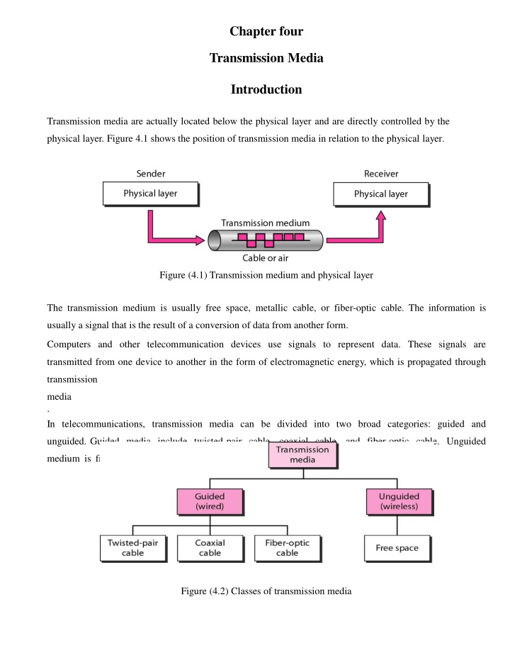
Chapter four Transmission Media Introduction Transmission media are actually located below the physical layer and are directly controlled by the physical layer. Figure 4.1 shows the position of transmission media in relation to the physical layer. Figure (4.1) Transmission medium and physical layer The transmission medium is usually free space, metallic cable, or fiber-optic cable. The information is usually a signal that is the result of a conversion of data from another form. Computers and other telecommunication devices use signals to represent data. These signals are transmitted from one device to another in the form of electromagnetic energy, which is propagated through transmission media . In telecommunications, transmission media can be divided into two broad categories: guided and unguided. Guided media include twisted-pair cable, coaxial cable, and fiber-optic cable. Unguided medium is free space. Figure 4.2 shows this taxonomy. Figure (4.2) Classes of transmission media
GUIDED MEDIA Which are those that provide a conduit from one device to another, include coaxial cable, twisted-pair cable, and fiber-optic cable.Twisted-pair and coaxial cable use metallic (copper) conductors that accept and transport signals in the form of electric current. Optical fiber is a cable that accepts and transports signals in the form of light. Coaxial Cable: - Coaxial cable (or coax) carries signals of higher frequency ranges than those in twisted pair cable, in part because the two media are constructed quite differently. coax, has a single, coated copper wire center and an outer metal mesh that acts as both a grounding circuit and an electromagnetic shield to reduce interference. The outer layer is the plastic cable jacket, figure (4,3). Figure (4.3) Coaxial Cable Coaxial cables are categorized by their radio government (RG) ratings. Each RG number denotes a unique set of physical specifications, including the wire gauge of the inner conductor, the thickness and type of the inner insulator, the construction of the shield, and the size and type of the outer casing. Each cable defined by an RG rating is adapted for a specialized function, as shown in Table (4, 1). Table (4,1) Categories of coaxial cables
To connect coaxial cable to devices, we need coaxial connectors. The most common type of connector used today is the Bayone-Neill-Concelman (BNC), connector,Figure (4.4). Figure (4.4) BNC connectors Twisted-Pair Cable: -A twisted pair consists of two conductors (normally copper), each with its own plastic insulation, twisted together, as shown in Figure 4.5. Figure (4.5) Twisted-pair cable One of the wires is used to carry signals to the receiver, and the other is used onlyas a ground reference. The receiver uses the difference between the two. Twisting the pairs of wire inside thecable reduce the noise and interference. The most common twisted-pair cable used in communications is referred to as unshielded twisted- pair (UTP). STP cable combines two methods of noise reduction by twisting the pairs of wire inside the cable to reduce interference and then shielding the cable in a wire mesh. STP can still be useful in installations where electromagnetic interference (EMI) is an issue, but STP cable is much more expensive than other available cable, so its use is quite limited at this time.Figure (4.6) shows the difference between UTP and STP.
Figure (4.6) UTP and STP cables The Electronic Industries Association (EIA) has developed standards to classify unshielded twisted-pair cable into seven categories. Categories are determined by cable quality, with 1 as the lowest and 7 as the highest. Each EIA category is suitable for specific uses. Table (4.2) shows these categories. Table (4.2) Categories of unshielded twisted-pair cables
The most common UTP connector is RJ45 (RJ stands for registered jack), as shown in Figure (4.7). The RJ45 is a keyed connector, meaning the connector can be inserted in only one way. Figure (4.7) UTP connector Twisted-pair cables are used in telephone lines to provide voice and data channels. Fiber-Optic Cable: - At the physical layer, diverse technologies can perform the same function of data transfer. Fiber-optic cable is very different from copper, yet both effectively carry data over networks. Whereas copper uses electrical voltage to represent data on the wire, fiber-optic cable uses light pulses conducted through special glass conductors to carry data. The cable is engineered to be as pure as possible and to allow reliable light signals to traverse the medium. Light travels in a straight line as long as it is moving through a single uniform substance. If a ray of light traveling through one substance suddenly enters another substance (of a different density), the ray changes direction. Figure (4.8) shows how a ray of light changes direction when going from a dense to a less dense substance. Figure (4.8) Fiber optics: Bending of light ray
Optical fibers use reflection to guide light through a channel. A glass or plastic core is surrounded by a cladding of less dense glass or plastic. The difference in density of the two materials must be such that a beam of light moving through the core is reflected off the cladding instead of being refracted into it. See Figure (4.9). Figure (4.9) Optical fiber Current technology supports two modes (multimode and single mode) for propagating light along optical channels, each requiring fiber with different physical characteristics. Multimode can be implemented in two forms: step-index or graded-index (see Figure 4.10). Figure (4.10) Propagation modes Multimode is so named because multiple beams from a light source move through the core in different paths. How these beams move within the cable depends on the structure of the core, as shown in Figure (4.11). In multimode step-index fiber, the density of the core remains constant from the center to the edges. A beam of light moves through this constant density in a straight line until it reaches the interface of the core and the cladding. At the interface, there is an abrupt change due to a lower density; this alters the angle of the beam's motion. The term step index refers to the suddenness of this change, which contributes to the distortionof the signal as it passes through the fiber.
A second type of fiber, called multimode graded-index fiber, decreases this distortion of the signal through the cable. The word index here refers to the index of refraction. As we saw above, the index of refraction is related to density. A graded-index fiber, therefore, is one with varying densities. Density is highest at the center of the core and decreases gradually to its lowest at the edge. Figure (4.11) shows the impact of this variable density on the propagation of light beams. Single-Mode Single mode uses step-index fiber and a highly focused source of light that limits beams to a small range of angles, all close to the horizontal. The singlemode fiber itself is manufactured with a much smaller diameter than that of multimode fiber, and with substantially lowers density (index of refraction). The decrease in density results in a critical angle that is close enough to 90 to make the propagation of beams is almost horizontal. In this case, propagation of different beams is almost identical, and delays are negligible. All the beams arrive at the destination "together" and can be recombined with little distortion to the signal (see Figure 4.11). Figure (4.11) Modes
There are three types of connectors for fiber-optic cables, as shown in Figure (4.12).The subscriber channel (SC) connector is used for cable TV. It uses a push/pull locking system. The straight-tip (ST) connector is used for connecting cable to networking devices. It uses a bayonet locking system and is more reliable than SC. MT-RJ is a connector that is the same size as RJ45. Figure (4.12) Fiber-optic cable connectors Fiber-optic cable is often found in backbone networks because its wide bandwidth iscost-effective. Today, with wavelength-division multiplexing (WDM), we can transfer data at a rate of 1600 Gbps. Some cable TV companies use a combination of optical fiber and coaxial cable, thus creating a hybrid network. Optical fiber provides the backbone structure while coaxial cable provides the connection to the user premises. Advantages Fiber-optic cable has several advantages over metallic cable (twistedpair or coaxial). Higher bandwidth. Fiber-optic cable can support dramatically higher bandwidths (and hence data rates) than either twisted-pair or coaxial cable. Currently, data rates and bandwidth utilization over fiber-optic cable are limited not by the medium but by the signal generation and reception technology available. Less signal attenuation. Fiber-optic transmission distance is significantly greater than that of other guided media. A signal can run for 50 km without requiring regeneration. We need repeaters every 5 km for coaxial or twisted-pair cable. Immunity to electromagnetic interference. Electromagnetic noise cannot affect fiber-optic cables. Resistance to corrosive materials. Glass is more resistant to corrosive materials than copper. Light weight. Fiber-optic cables are much lighter than copper cables. Greater immunity to tapping. Fiber-optic cables are more immune to tapping than copper cables. Copper cables create antenna effects that can easily be tapped.
Advantages Fiber-optic cable has several advantages over metallic cable (twisted pair or coaxial). Higher bandwidth. Fiber-optic cable can support dramatically higher bandwidths (and hence data rates) than either twisted-pair or coaxial cable. Currently, data rates and bandwidth utilization over fiber-optic cable are limited not by the medium but by the signal generation and reception technology available. Less signal attenuation. Fiber-optic transmission distance is significantly greater than that of other guided media. A signal can run for 50 km without requiring regeneration. We need repeaters every 5 km for coaxial or twisted-pair cable. Immunity to electromagnetic interference. Electromagnetic noise cannot affect fiber-optic cables. Resistance to corrosive materials. Glass is more resistant to corrosive materials than copper. UNGUIDED MEDIA: WIRELESS Unguided media transport electromagnetic waves without using a physical conductor. This type of communication is often referred to as wireless communication. Signals are normally broadcast through free space and thus are available to anyone who has a device capable of receiving them. Figure (4.13) shows the part of the electromagnetic spectrum, ranging from 3 kHz to 900 THz, used for wireless communication. Figure (4.13) Electromagnetic spectrum for wireless communication The section of the electromagnetic spectrum defined as radio waves and microwaves is divided into eight ranges, called bands, each regulated by government authorities. These bands are rated from very low frequency (VLF) to extremely highfrequency (EHF). Table (4.3) lists these bands, their ranges, propagation methods, and some applications.
Table (4.3) Bands The IEEE and telecommunications industry standards for wireless data communications cover both the data link and physical layers. Following are four common data communications standards that apply to wireless media: Standard IEEE 802.11: Commonly referred to as Wi-Fi, 802.11 is a wireless LAN (WLAN) technology that uses a contention or nondeterministic system with a carrier sense multiple access/collision avoiding (CSMA/CA) media access process. Standard IEEE 802.15:Wireless Personal-Area Network (WPAN): Commonly known as Bluetooth, 802.15 uses a device-pairing process to communicate over distances from 1 to 100 meters. Standard IEEE 802.16: Commonly known as WiMAX (Worldwide Interoperability for Microwave Access), 802.16 uses a point-to-multipoint topology to provide wireless broadband access. Global System for Mobile Communication (GSM): Includes physical layer specifications that enable the implementation of the Layer 2 General Packet Radio Service (GPRS) protocol to provide data transfer over mobile cellular telephony networks. Other wireless technologies, such as satellite communications, provide data network connectivity for locations without another means of connection. Protocols including GPRS enable data to be transferred between earth stations and satellite links.
In each of these examples, physical layer specifications are applied to areas that include datatoradio signal encoding, frequency and power of transmission, signal reception and decoding requirements, and antenna design and construction.


 UTP and STP cables")


 Bands")