Toyota 5FBC13-30 Battery Forklift Service Repair Manual Instant Download
Please open the website below to get the complete manualnn//
Download Presentation

Please find below an Image/Link to download the presentation.
The content on the website is provided AS IS for your information and personal use only. It may not be sold, licensed, or shared on other websites without obtaining consent from the author. Download presentation by click this link. If you encounter any issues during the download, it is possible that the publisher has removed the file from their server.
E N D
Presentation Transcript
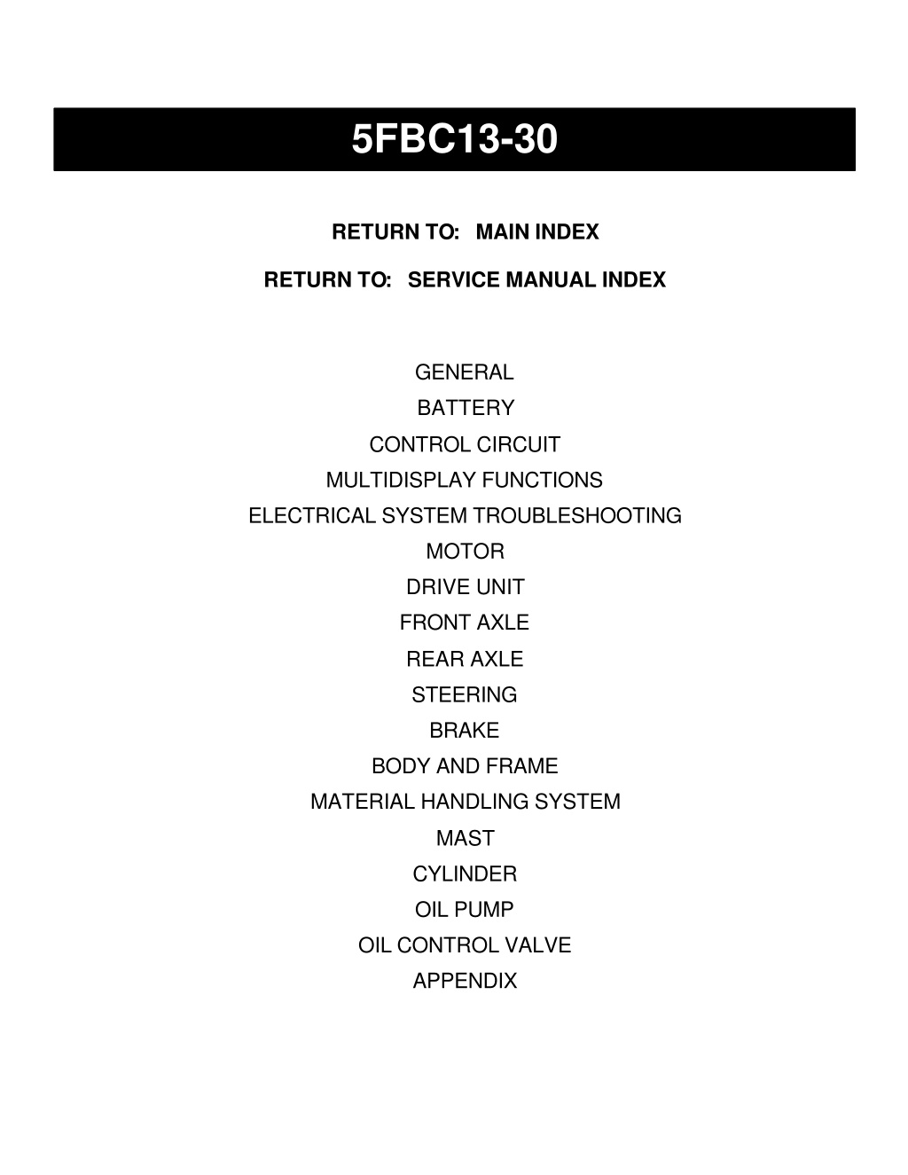
5FBC13-30 RETURN TO: MAIN INDEX RETURN TO: SERVICE MANUAL INDEX GENERAL BATTERY CONTROL CIRCUIT MULTIDISPLAY FUNCTIONS ELECTRICAL SYSTEM TROUBLESHOOTING MOTOR DRIVE UNIT FRONT AXLE REAR AXLE STEERING BRAKE BODY AND FRAME MATERIAL HANDLING SYSTEM MAST CYLINDER OIL PUMP OIL CONTROL VALVE APPENDIX
FOREWORD This manual covers the service procedures of the TOYOTA BATTERY FORKLIFT 5FBC13 - 30 Series. Please use this manual for providing quick, correct servicing of the corresponding forklift models. This manual deals with the above models as of November 1991. Please understand that disagreement can take place between the descriptions in the manual and actual vehicles due to change in design and specifi- cations. Any change or modifications thereafter will be informed by Toyota Industrial Vehicles' Parts & Service News. TOYOTA MOTOR CORPORATION
SECTION INDEX 0 BATTERY CONTROL CIRCUIT MULTIDISPLAY FUNCTIONS ELECTRICAL SYSTEM TROUBLESHOOTING 1 SECTION 1 NAME 8 A DRIVE UNIT FRONT AXLE REAR AXLE STEERING BRAKE BODY & FRAME MATERIAL HANDLING SYSTEM MAST CYLINDER OIL PUMP OIL CONTROL VALVE APPENDIX 8
https://www.ebooklibonline.com Hello dear friend! Thank you very much for reading. Enter the link into your browser. The full manual is available for immediate download. https://www.ebooklibonline.com
GENERAL Page .............................................. EXTERIOR VIEWS VEHICLE MODEL ................................................ 0-3 FRAME NUMBER ................................................ 0-4 HOW TO READ THIS MANUAL EXPLANATION METHOD ..................................... 0-5 TERMINOLOGY .................................................. 0-6 ABBREVIATIONS ............................................... 0-6 LIST OF ABBREVIATIONS AND SYMBOLS ............. 0-7 OPERATIONAL TIPS ........................................ 0-8 CIRCUIT TESTER ............................................... 0-9 STANDARD BOLT & NUT TIGHTENING .......................................................... TORQUE 0-2 ......................... 0-5 0-11 BOLT STRENGTH TYPE IDENTIFICATION METHOD ........................................................ 0-11 TIGHTENING TORQUE TABLE ............................... 0-12 PRECOAT BOLTS ............................................... 0-13 HIGH PRESSURE HOSE FITTING .................................... TIGHTENING TORQUE WIRE ROPE SUSPENSION ANGLE LIST ............. 0-14 SAFE LOAD FOR EACH WlRE ROPE ...................................... SUSPENSION ANGLE COMPONENTS WEIGHT .................................... 0-15 RECOMMENDED LUBRICANTS ........................................... AND CAPACITIES ....................................... LUBRICATION CHART PERIODIC MAINTENANCE PERIODIC REPLACEMENT OF PARTS AND LUBRICANTS .......................................... 0-23 0-13 0-14 0-16 0-17 ................................. 0-18
EXTERIOR VIEWS 1 I 1 Front V ~ e w I I Rear View
0-3 VEHICLE MODEL Voltage v Model Control Circu~t 36 or 48 t T t 5FBC 13 Standard MCS-Ill t t . 1.25 ton Dustproof 30-5FBC 1 3 I ton series Standard 5FBC 1 5 1.5 ton T t t 30-5FBC 1 5 Dustproof T t 5FBC 1 8 Standard 1.75 ton 30-5FBC 18 Dustproof t t t t t t t t 7 t t t t t 30-5FBC20 Dustproof 2.0 ton 5FBCH20 Standard 2 ton 30-5FBCH20 Dustproof series 5FBC25 Standard 30-5FBC25 Dustproof 2.5 ton 5FBCH25 Standard 30-5FBCH25 Dustproof
FRAME NUMBER Vehicle model 5FBC15-10011 5FBC 1 5E 1001 1 5FBC25-10011 5FBC25E10011 5FBCH20 5FBCH25 5FBC28 5FBC30 30-5FBC 1 3 30-5FBC 1 5 30-5FBC I 8 5FBCH25-10011 5FBCH25E10011 3 ton series 5FBC30-10011 5FBC30E10011 1 ton series 305FBC15-10011 305FBC15E10011 30-5FBC20 30-5FBC25 305FBC25-10011 305FBC25E10011 2 ton series 30-5FBCH20 30-5FBCH25 305FBCH25-10011 305FBCH25E10011 3 ton series 30-5FBC28 30-5FBC30 305FBC30-10011 305FBC30E10011
HOW TO READ THIS MANUAL EXPLANATION METHOD Operation procedure (1 ) The operation procedure is described in either pattern A or pattern B below. Pattern A: Explanation of each operation step with a photo or illustration. Pattern B: Explanation of operation procedure by indicating step numbers in one illustration, fol- lowed by explanation of cautions and notes summarized as point operations. 1. Example of description in pattern B / Tightening torque unit T = N.m (kg-cm)[ft-lbl DISASSEMBLY-INSPECTION.REASSEMBLY If a place or part cannot be indi- cated directly, the part name is described on the either side of the illustration. Example: 1 Piping I I Oil Pump Disassembly Procedure Disassembly Procedure 1 Remove the cover. [Point 11 2 Remove the bush [Point 2 1 - Operation explained on a laterpage 3 Remove the gear. / Point operations Explanation of key point for operation with an illustration 4 Disassembly: Put a match mark when removing the pump cover. I [Point I I [Point 21 Inspection: Measure the bush inside diameter. Bush inside diameter limit:19.12 mm (0.7528 in)
FIG number in parts catalog I 2. How to read components figures (1) The components figure use the illustra- tion in the parts catalog for the vehicle model. Please refer to the catalog for checking the part name. The number at the right shoulder of each components figure indicates the Fig. number in the parts catalog. (Example) 3. Matters omitted in this manual (1) This manual omits description of the following jobs, but perform them in actual operation: @ Cleaning and washing of removed parts as required @ visual inspection (Partially described) TERMINOLOGY Caution: lmportant matters of which negligence may cause accidents. Be sure to observe them. Note: lmportant items of which negligence may cause accidents or matters in operation procedure re- quiring special attention. Standard: Values showing allowable range in inspection and adjustment. Limit: Maximum or minimum allowable value in inspection or adjustment.
LIST OF ABBREVIATIONS AND SYMBOLS Symbol BATT Name Symbol FRY H Name Name Symbol MScH MW Charger Magnet Switch Field Weakning Contactor Computer Print Board SPS Print Board Working Pilot Lamp Fan Resistor Field Weakning Resistor Regenerative Resistor Battery Buzzer Drivelpump Absorber Capacitor Charger Forward Chime Reverse Chime Drivelpump Current Flasher Relay Horn Back-up Lamp, LH Back-up Lamp, RH Clearance Lamp, LH Clearance Lamp, RH Flasher Lamp, LH Flasher Lamp, LH (Rear) B z CADIP L , , . , L , , . , PBcpu PBsps P L , RF RFW RG CH CHI, CHIR CSDIP LC-L LF-L L , , , Flasher Lamp, RH RADIP Drivelpump Absorber Head Lamp, LH Head Lamp, RH Rotaly Forward Lamp Rotaly Reverse Lamp Surge Absorber Drive SIT Driver Pump SIT Driver Lequid Level Sensor Snubber No.1 Speed Sensor Steering Torque Sensor DcH DC-SDD DC-DC Converter & Source Drive (Drive) DC-SDP DC-DC Converter & Source Drive (Pump) DF112 FLY-WHEEL Diode, Charger Diode SDD SDP SSP Brake Limit Switch Tilt Limit Switch irection Switch everse Direction Switch Main Transistor Forward Contactor Pump Contactor
OPERATIONAL TIPS 1. Safe operation (1 After jacking up, always support with rigid stands. (2) When hoisting the vehicle or its heavy component, use wire rope(s) with a sufficient reserve in load capacity. (3) Always disconnect the battery plugs before the inspection or servicing of electrical parts. 2. Tactful operation (1 Prepare the mechanic tools, necessary measuring instruments (circuit tester, megger, oil pres- sure gauge, etc.) and SSTs before starting operation. (2) Before disconnecting wiring, always check the cable color and wiring state. (3) When overhauling functional parts, complicated portions or related mechanisms, arrange the parts neatly to prevent confusion. (4) When disassembling and inspecting such a precision part as the control valve, use clean tools and operate in a clean location. (5) Follow the described procedures for disassembly, inspection and reassembly. (6) Replace, gaskets, packings and O-rings with new ones each time of disassembly. (7) Use genuine Toyota parts for replacement. (8) Use s If no tightening torque is specified, tighten the bolt or nut according to the standard tightening torque table. d bolt and nuts. Observe the specified tightening torque at the time of reassembly. 3. Grasping the troule state When a trouble occurs, do not attempt immediate disassembly or replacement but first check if the trouble requires disassembly or replacement for remedying.
CIRCUIT TESTER Circuit testers are available in both the analog and digital types. The should be used selectively accord- ing to the purpose of measurement. Analog type: This type is convenient for observing movement during operation, but the measured value should only be used for reference or rough judgement. Digital type: Fairly accurate reading is possible, but it is difficult to observe the variation or move- ment. 1. Difference in measurement results with the digital type and analog type * The result may be different between measurements with the analog type and digital type. Al- ways use a circuit tester according to its operation manual. Cautions when the polarities are dif- ferent between the analog type and digital type are described below. Circuit tester range: Analog type -t kohm range Digital type + 2 Mohm range Forward direction Reverse direction Black robe Red probe Measurement result exampie As seen from the example above, the measurement results with the analog and digital types are re- verse. In measurement with a digital type circuit tester, therefore, use the tester probes as shown be- low. Forward direction Reverse direction
2. Difference in result of measurement with circuit tester The circuit tester power supply voltage depends on the tester type. 1.5V, 3.OV or 6.OV is used. The resistance of a semiconductor such as a diode varies with the circuit tester power supply voltage. The diode characteristics are shown in the figure below. The resistance values of the same semiconductor mea- sured with two types of circuit testers having different power supply voltages are different. ( m ~ ) 5 4 Current in forward direction This manual describes the results of measurement with a circuit tester whose power supply voltage is 3.0 V. 3 2 1 0 0.1 0.2 0.3 0.4 0.5 0.6 0.7 0.8 Voltage in forward direction 3. Difference in measurement result by measurement range (analog type) In the analog type circuit tester, changing the measurement range switches over the internal circuit to vary the circuit resistance. Even when the same diode is measured, the measurement result varies with the measurement range. Always use the range described in the repair manual for measurement. t l Variable resistor Current Resistor Range: x 10 Resistor Range: x I Power source: 1.5 V Red Black
STANDARD BOLT & NUT TIGHTENING TORQUE Standard bolt and tightening torques are not indicated. Judge the standard tightening torque as shown below. 1. Find out the type of the bolt from the list below and then find the bolt tightening torque from the table. 2. The nut tightening torque can judged from the mating bolt type. BOLT STRENGTH TYPE IDENTIFICATION METHOD 1. 2. Identification by bolt shape Identification by part No. Bolt head No. 9 16 1 1-40625 Diameter (mm) Two protruding Two protruding Three protruding 92 1 32-406 1 4 Diameter (mm) Stud bolt 6T Grooved
0-1 2 TIGHTENING TORQUE TABLE
PRECOAT BOLTS (Bolts with seal lock agent coating on threads) Do not use the precoat bolt as it is in either of the fol- lowing cases. (a) After is removed. (b) When the precoat bolt is moved (loosened or tight- ened) by tightness check, etc. 1. Note: For torque check, use the lower limit of the allowable tight- ening torque range. If the bolt moves, retighten it according to the steps below. 2. Method for reuse of precoat bolts (1) Wash the bolt and threaded hole. (The threaded hole must be washed even for replacement of the bolt.) (2) Parfectly dry the washed parts by air blowing. (3) Coat the specified seal lock agent to the threaded portion of the bolt. HIGH PRESSURE HOSE FITTING TIGHTENING TORQUE When connecting a high pressure hose, wipe the hose fitting and mating nipple contact surfaces with clean cloth to remove foreign matters and dirt. Also check no dent or other damage on the contact surfaces before installation. 1. When connecting a high pressure hose, hold the hose to align the fitting with the nipple and tighten the fitting. 2. 3. The maximum tightening torque must not exceed twice the standard tightening torque. Hose inside diameter mm (in) Standard tightening torque N.m (kgf-cm) [ft-lbfl Nominal diameter of screw Tightening range Standard 24 - 26 ( 240 - 270) [17.4 - 19.51 47 - 52 ( 480 - 530) 134.7 - 38.31 56 - 62 ( 570 - 630) [41.2 - 45.61 56 - 62 ( 570 - 630) [41.2 - 45.61 112-123(1140-1250)[82.5- 90.41 130 - 144 (1330 - 1470) I96.2 - 106.41 24 - 26 ( 240 - 270) 117.4 - 19.51 47 - 52 ( 480 - 530) 134.7 - 38.31 56 - 62 ( 570 - 630) [41.2 - 45.61 112 - 123 (1 140 - 1250) l82.5 - 90.41 130 - 144 (1330 - 1470) 196.2 - 106.41 6 (0.24) 25 ( 250) [ 18.11 7116 - 20UNF 9 (0.35) 49 ( 500) [ 36.21 9116 - 18UNF 12 (0.47) 314 - 16UNF 59 ( 600) [ 43.41 12 (0.471, 15 (0.59) 59 ( 600) [ 43.41 718 - 14UNF 19 (0.75) 118(1200)[ 86.81 1.1116-12UNF 25 (0.98) 137 (1400) [101.3] 1.5116 - 12UNF 6 (0.24) 25 ( 250) [ 18.11 PF1 14 9 (0.35) 49 ( 500) [ 36.21 PF318 12 (0.47) 59 ( 600) [ 43.41 PF112 19 (0.75) 118 (1 200) [ 86.81 PF314 25 10.98) 137 (1400) [101.3] PF 1
WlRE ROPE SUSPENSION ANGLE LIST Suspension method Lifting angle Compres- sion Compres- sion Suspension method L~fting angle Tension Tension 1.41 time 1 .OO time 0 time 0 O I .OO time 90 O 2' 1.04 time 0.27 time SAFE LOAD FOR EACH WIRE ROPE SUSPENSION ANGLE Unit: N (ton) [Ibl Single-rope suspension 0 O 3040 (0.31) [683.6] 4410 (0.45) [992.3] 6960 (0.71) [1565.6] 10980 (1.12) [2469.5] 13730 (1.4) [3087] Four-rope suspension Rope diameter Cutting load Two-rope suspension 60 O 10400 (1.06) [23371 15300 (1.56) [34401 23540 (2.4) [52921 37270 (3.8) t83791 47070 (4.8) [I 05841 90 O 8630 (0.88) [ I 9401 12550 (1.28) 123221 19610 (2.0) 144101 29420 (3.0) [66151 37270 (3.8) [83791 30 O 11770 (1.2) [2646] 17060 (1.74) [3937] 26480 (2.7) [59541 41190 (4.2) [92611 52960 (5.4) [ I 19071 60 O 5200 (0.53) [ I 1691 7650 (0.78) [ I 7201 11770 (1.2) [2646] 18630 (1.9) [41901 23540 (2.4) [5292] 90 O 4310 (0.44) [970] 6280 (0.64) [ I 41 I ] 9810 (1.0) [2205] 14710 (1.5) [3308] 18630 (1.9) [4190] 0 O 0 O 6080 (0.62) [ I 3671 8830 (0.9) [I 9851 14020 (1.43) [3153] 21570 (2.2) 148511 27460 (2.8) [6174] 30 O 5880 (0.6) [ I 3231 8530 (0.87) [ I 91 81 13440 (1.37) [30211 21280 (2.1) [46311 26480 (2.7) [5954] 12160 (1.24) [2734] 17650 (1.8) [3969] 27460 (2.8) [61741 43150 (4.4) I97021 54920 (5.6) [I 23481 21380 (2.18) 148071 31480 (3.21 ) [7078] 49230 (5.02) [ I 1.691 76880 (7.84) [I73871 96400 (9.83) [21675] 6 mm (0.24 in) 8 mm (0.32 in) 10 mm (0.4 in) 12.5 mm (0.5 in) 14 mm (0.56 in)
COMPONENTS WEIGHT Weight N (kg) [Ibl Model Item Approx. 735 (75) 11651 Only dustproof model: Approx. 834 (85) [I871 1 ton series Drive Approx. 1079 (1 10) 12431 2 ton series 3 ton series Motor Approx. 1079 (1 10) [2431 Approx. 441 (45) [991 1 ton series Approx. 637 (65) 11431 2 ton series Material handling Approx. 637 (65) [I431 3 ton series Approx. 2746 (280) 161 7 1 5FBC 1 3 Approx. 431 5 (440) [6701 5FBC 1 5 Balance weight Mast W/ lift bracket (with lift cylinder, less back rest and fork)
0-1 6 RECOMMENDED LUBRICANTS AND CAPACITIES Capacity Application Type 7.0 1 (1.85 US gal.) STD: Hypoid gear oil SAE85W-90 (API GL-4) Differential & transmission 1 ton series 7.5 1 (1.98 US gal.) 45s: Hypoid gear oil w (API GL-4) 2 - 3 ton series "16 1 (4.2 US gal.) ""21 1 (5.5 US gal.) "20 1 (5.3 US gal.) ""26 1 (6.9 US gal.) STD: Hydraulic oil IS0 VG32 Hydraulic (total) 1 ton series 45s: MIL-H-5606-D 2 - 3 ton series STD: SAE J-1703 DOT-3 45s: Brake fluid artic S Brake line Proper quantity STD: MP grease No.2 45s: Esso beacon 325 Chassis part Proper quantity 45s: Refrigerator specification vehicle *: For 3000 mm (1 18 in) maximum fork height **: For 6000 mm (236 in) maximum fork height
LUBRICATION CHART 1. Chain I lnspect every 8 hours (daily) 2. Mast support bushing I1 lnspect every 40 hours (weekly) 3. Tilt cylinder front pin 111 lnspect every 170 hours (monthly) Front wheel bearing lnspect every 1000 hours (6 4. monthly) IV Differential & transmission 5. V 0 lnspect and service lnspect every 2000 hours (annually) 6. Brake fluid reservoir tank 7. Tilt steering locking mechanism Re~lace 8. Tilt steering universal joint 9. Oil tank MP grease 1. 10. Rear wheel bealing 2. Engine oil 1 1. Steering knuckle king pin Hypoid gear oil 3. 12. Rear axle beam front Hydraulic oil 4. 13. Rear axle cylinder rod joint (1 ton series) 5. Brake fluid 14. Rear axle beam rear * Located on right and left sides Lubrication Chart
PERIODIC MAINTENANCE INSPECTION METHOD I: Inspection. Repair or replacement if required. M: Measurement. Repair or adjustment if required. T : Retightening C: Cleaning * : For new vehicle * 1 : Flaw detector L: Lubrication 6 3 12 1 Months Inspection Period Item 2000 170 500 1000 Hours ELECTRICAL SYSTEM 0 0 0 0 0 0 0 0 0 0 0 0 0 0 0 I Abnormal sound during revolution T Loose terminal M Insulation resistance Motor I Brush wear and sliding contact status I Commutator fouling and damage Battery fluid level Battery fluid specific gravity Loose terminal Abnormality at top of battery and Timer operation 0 0 0 0 I 0 0 0 Terminal loosening Charger M Operating voltage measurement Magnet switch function, contact fouling and roughening 0 I 0 0 0 0 I Loose contact, damage and wear Auxiliary contact function, fouling and wear 0 0 0 0 I Magnet contactor 0 0 0 0 0 0 I Arc chute installation status I Timing and functioning I Loose coil installation I Loose main circuit lead installation 0 0 0 0 0 0 I Timing and operating function Microswitch I Damage and loose installation
1 3 6 12 Months Inspection Period Item 170 0 0 0 500 0 0 0 1000 0 0 0 2000 0 0 0 0 0 Hours Operating conditions and damage I Direction lever Operation I Controller Inside fouling and damage C M Overcurrent limit valve 0 0 0 Fuse I Loosening Damage of wiring harness and loose clamp 0 0 0 0 I Wiring (including charging 0 0 I 0 0 Loose connection and taping status Battery connector damage and connection status 0 0 0 0 I 0 0 0 0 Accelerator I Operating and damage POWER TRAIN 0 0 0 0 I Oil leak Differential, Loose rim and hub nuts Tire groove depth Metal chips, pebbles and other foreign matter trapped in tire grooves Rim and disc wheel damage Abnormal sound and looseness of front wheel bearing beam Rear axle Looseness of axle beam in vehicle longitudinal direction 0" 0 M
Months 3 6 12 1 Inspection Period Item Hours 170 500 1000 2000 STEERING SYSTEM Play and looseness I 0 0 0 0 0 0 0 0 0 0 0 0 0 0 0 0 0 0 0 0 0 0 0 0 0 Steering wheel Function I Oil leak I Gear box Looseness of mounting T Oil leak I Power steering Damage of power steering hose I I 0 0 King pin looseness 0 Knuckle Cracks and deformation I Wheel alignment M Steering shaft Left and right turning angle M BRAKING SYSTEM Rod and cable looseness and damage Drum wear and damage Brake drum and brake shoe Shoe operation condition Anchor pin rusting Return spring fatigue Automatic adjuster function I 0 0 0 Deformation, cracks and damage I Backing plate Loose mounting T
3 6 12 Months 1 Inspection Period Item 1000 Hours 2000 170 500 MATERIAL HANDLING SYSTEM I 0 0 0 0 Abnormality of fork and stopper pin Misalignment between left and right fork fingers I 0 0 0 Forks 0 I*' 0 Cracks at fork root and welded part Deformation and damage of each part and crack at welded part I 0 0 0 0 0 I 0 0 0 Mast and lift bracket looseness Wear and damage of mast support bush I 0 Mast and fork bracket Wear, damage and rotating condition of rollers 0 0 0 0 I 0 0 Wear and damage of roller pins I I 0 0 0 Wear and damage of mast strip Tension, deformation and damage of Chain lubrication Abnormality of chain anchor bolt Wear, damage and rotating condition Deformation and damage of rod, rod screw and rod end I 0 0 0 0 Cylinder 0 0 0 0 I Cylinder operation Natural drop and natural forward tilt (hydraulic drift) I 0 0 0 0 0 0 0 0 I Oil leak and damage Wear and damage of pin and cylinder bearing 0 I 0 0 0 Cylinder 0 0 0 0 0 0 0 0 0 0 M 0 0 0 0 0 0 0 0 0 0 Lifting speed I Uneven movement Oil pump I Oil leak and abnormal sound I Oil level and contamination Hydraulic oil tank Tank and oil strainer C 0 0 I Oil leak
3 6 12 1 Months Inspection Period Item 2000 0 0 0 0 500 0 0 0 1000 0 0 0 170 0 0 0 Hours I Loose linkage Control lever I Operation I Oil leak M Oil control valve Relief pressure measurement Relief valve and tilt lock valve functions 0 0 0 0 I 0 0 0 0 0 0 0 0 0 0 0 0 0 0 0 0 I Oil leak I Deformation and damage Hydraulic piping T Loose joint I Hoise tension and twisting SAFETY DEVICES, ETC. 0 0 0 0 0 0 0 0 I Cracks at welded portion Head guard I Deformation and damage Loosening of mounting ' Functions Function and mounting condition 0 0 0 0 0 0 $ 0 0 0 0 0 0 lnstrunenrs I 0 0 0 0 0 0 0 I Back up buzzer I Dirt, damage Rear-view mirror I Rear reflection status I Seat Loosening and damage of mounting Damage and cracks of frame, cross members, etc. 0 I Body 0 0 T Bolt looseness 0 0 0 Other L Grease up
Suggest: For more complete manuals. Please go to the home page. https://www.ebooklibonline.com If the above button click is invalid. Please download this document first, and then click the above link to download the complete manual. Thank you so much for reading
0-23 PERIODIC REPLACEMENT OF PARTS AND LUBRICANTS 3 6 12 Months 1 Inspection (operating hours or months, whichever is earlier) 1000 a 2000 a 170 500 Hours Brake fluid Hydraulic oil a Hydraulic oil return filter (New vehicle) Differential and transmission oil Wheel bearing grease Master cylinder rubber parts
BATTERY Page SERVICE STANDARDS ........................................ 1-2 DISPLAY INDICATION ........................................... 1-2 OVERDISCHARGE ALARM FUNCTION ..................... 1-2 BATTERY COMPARTMENT & MINIMUM WEIGHT REQUIRED ........................................ 1-3 TROUBLESHOOTING ........................................... 1-4 BATTERY ASSY ................................................... 1-5 INSPECTION ........................................................ 1-6
https://www.ebooklibonline.com Hello dear friend! Thank you very much for reading. Enter the link into your browser. The full manual is available for immediate download. https://www.ebooklibonline.com


