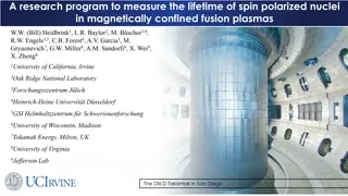
Spin rotator design and spin matching

S
p
i
n
r
o
t
a
t
o
r
d
e
s
i
g
n
a
n
d
s
p
i
n
m
a
t
c
h
i
n
g
V. Ptitsyn, S.Tepikian
BNL
EIC electron spin rotators
•
Electron energy range: 5-18 GeV
•
A HERA-type rotator (based on sequence of
vertical and horizontal bend) creates meter scale
orbit excursion at lower energies.
•
The rotator design capable to operate in all
energy range is based on the combination of
solenoidal and horizontal bending magnets.
eRHIC spin rotator
C-type bending configuration
j
–
spin rotation angle in solenoids
i
–
spin rotation angle in bends
Spin rotator: spin rotation angle
definitions
bend1
1
=
0
0
=
a
bending angles
Relations between solenoidal rotation angles (
and horizontal bend spin
rotation angles (
) to convert vertical spin to longitudinal:
Selecting rotator parameters
In gray areas of (
1
,
) plane the spin transformation from vertical
to longitudinal can not be realized
•
Spin rotation angles (
1
,
) are related with bend
angle values:
1
=
a
=
a
•
Thus, any straight line passing through the origin
point corresponds to varying electron energy at
fixed dipole bending angles.
•
For instance, the red line on the plot corresponds
to varying energy at fixed and equal
and
15 GeV point
With this rotator design example the longitudinal polarization at 18 GeV
energy
can not be realized
, since energy range is limited (5-15 GeV)
Achieving largest continuous energy
range
•
Red lines
=2
and
=2
span over
longest continuous good parameter intervals
•
Thus, these lines (and bend angle relations)
provides largest possible continuous energy
range:
Maximum-to-minimum energy ratio = 5
•
=2
line leads to smaller values of required
solenoid fields, than
=2
Thus this is a preferable choice for EIC rotator
5 GeV point
(3.6 GeV)
25 GeV point
(18 GeV)
= 92.27 mrad
46.14 mrad
Two examples of continuous ranges covering
all EIC energies (using
=2
line )
5-25 GeV:
3.6-18 GeV:
= 128.15 mrad
64.08 mrad
Spin rotator: required solenoid fields
Provides longitudinal polarization in IP throughout the whole energy range.
Calls for SC solenoids
with up to 7T field
Polarization evolution in electron ring
Synchrotron radiation determines the polarization evolution through Sokolov-Ternov spin-
flip emission and spin diffusion caused by quantum emission of S photons. Both processes
combined define the equilibrium polarization P
eq
and polarization relaxation time t.
Derbenev-Kondratenko:
(1973)
(taken at const x, x’, y, y’)
Depolarization caused by spin diffusion is
defined by a derivative of invariant spin
field over :
First-order spin perturbation
consideration
The magnetic fields on design orbit define the periodical spin solution
n
0
and two others
spin eigenvectors
k
0
=
l
0
+i
m
0
,
k
0
*
.
l
0
,m
0
,n
0
form normalized triad convenient for considering spin motion perturbations.
In the first order spin perturbation
by momentum deviation or betatron motion is
described by the following equation:
where components perturbation precession vector
w
(neglecting terms of order of
anomalous magnetic moment
a
) are:
With proper periodical conditions the solution of this equation gives the invariant spin field
in first order.
Exploring spin matching conditions
The goal:
eliminate (minimize) dependence of
the spin invariant field (
) on horizontal
betatron amplitude
A
x
and energy deviation
outside the rotator system.
Thus avoiding any spin dynamics distortion by synchrotron radiation in the arc bends.
The following integral over the whole spin rotator system must be made 0 for terms
proportional to
A
x
and
:
The orbital motion is considered in a standard form through components of betatron motion
eigen-vectors
f
I
and f
II
and dispersion functions
D
x
, D
y
:
Spin matching conditions for
solenoidal rotators
We assumed following reasonable optics conditions:
-betatron coupling is fully compensated individually for each of four solenoidal insertions by
dividing each solenoid in two halves
and using set of quadrupoles/skew quadrupoles between
and around them
-the vertical dispersion function
D
y
does not leak into the horizontal bends
Then, using integration by parts one gets following set of spin matching conditions
(neglecting terms of order
a
):
where:
F
is either
f
I
or
D
entrance of first part
of solenoid
exit of second half
of solenoid
Direct energy effect spin matching
This term can be nullified either
by not allowing dispersion function
inside solenoids or by proper optics
This combination is completely defined by the
choice of bending angles of the dipoles and
solenoidal fields.
For S-type bending configuration
around IP and spin-up to spin-up
transformation through the whole
rotator system: automatically zero .
For C-type bending configuration around IR, used in
EIC, can be nullified at
a particular energy
with
following choice of rotator parameters:
1
=
4
= 0.524 rad,
2
=
3
= 2.094 rad
1
=
4
=
rad,
2
=
3
=
/2 rad
It makes sense to consider fully longitudinal
matching the rotators at EIC highest energy,
18 GeV
Contribution
from solenoids
Contribution from
IR an rotator dipoles
The rotator solution corresponding to full
direct energy spin match at 18 GeV
30 GeV point
But with this rotator design the longitudinal
polarization only realized down to 6 GeV energy.
Dipole bend angles:
= 76.89 mrad,
38.45 mrad
Solenoid strength:
1
= 0.524 rad,
2
= 2.094 rad
Solenoidal insertion with betatron spin
matching
Spin matching conditions related with betatron motion can be satisfied for each
individual solenoidal insertion, using two solenoid halves and (at least 6) quadrupoles
between them.
T
x,y
L
Realization of short solenoid insertion
14
V.5.3 lattice
Realization of long solenoid insertion
15
V5.3 lattice
However, present solution requires superconducting quadrupoles.
Thus, we are continuing to work on optics trying to find solution without SC quads
.
Example of d-function around the ring
for two lattices
pCDR’18 lattice
v5.2 lattice
Optimization of rotator layout for 18 GeV
resulted in good spin match into the arc
in v5.2.
However, sufficiently large d-function is
still present throughout IR.
Spin matching was not very good
•
Option 1: Minimized depolarization at 18 GeV. But limited energy range (to 6
GeV)
•
Option 2: covers 5-18 GeV energy range, but stronger depolarization is
expected
•
Option 3: covers 5-18 GeV energy range, but stronger depolarization is
expected
Three rotator design options for comparison
= 76.89 mrad
38.45 mrad
= 92.27 mrad
46.14 mrad
= 128.15 mrad
64.08 mrad
Option 1
Option 2
Option 3
Polarization Relaxation Time Comparison
(first-order calculation)
Conclusion:
Although the Option 1 demonstrates longer polarization relaxation times,
the times in the Option 2 is not much lower.
Both option 1 and 2 remains on the table as a possible implementation of rotator design.
Calculations are done at energies corresponding to 0.5 fractional spin tune
(17.84-17.89 GeV and 10.25-10.34 GeV depending on rotator option)
Polarization formulas
Sokolov-Ternov (ST)
Baier-Katkov-Strakhovenko (BKS)
BKS + kinetic polarization mechanism
Derbenev-Kondratenko (Full DK)
(with stochastic depolarization)
18 GeV lattices: disentangling different
contributions in the polarization
pCDR’18
v5.0
v5.2
v5.3
v5.3
no IR dipoles
pCDR’18
v5.0
v5.2
v5.3
v5.3
no IR dipoles
pCDR’18: eSR not yet fitted in the tunnel; Option 2 rotator
v5.0: eSR partially fitted in the tunnel; lattice with longer bends; Option 1 rotator
v5.2: eSR fully fitted in the tunnel, Option 1 rotator
v5.3: IR design layout adjustments, Option 1 rotator
v5.3 no IR dipoles: excluded (only for the analysis purposes) 0.44-0.46 T dipoles in IR6 and IR8
Energy used for calculation: 17.84 GeV (corresponding to ~.5 fractional spin tune)
10 GeV lattices: disentangling different
contributions in the polarization
Energy used for calculation: 10.25 GeV
v5.2
v5.3
v5.2
v5.3
Spin matching at 10 GeV is worse than at 18 GeV resulting in less asymptotic polarization.
But, it is not so important since the polarization relaxation time is very long at 10 GeV.
Kinetic polarization effect is notable for
both 10 GeV and 18 GeV lattices
Summary
EIC spin rotator design has been developed based on combination of
solenoidal and dipole magnets covering wide energy range required
by EIC
The design optimization continues:
reducing compensation quad strength
optimal selection of rotator configuration (two options)
The conditions for spin matching have been derived from spin-orbital
integrals and implemented in the rotator optics
Betatron related spin-matching can be done by using a special
transport matrix of solenoidal insertions
There is a rotator configuration that can provide full spin matching at
18 GeV, but its minimum energy is limited to 6 GeV
Alternative version of spin rotator is presently being evaluated, with
potential of reducing space taking by rotator system (and saving
cost). Please, see next talk by Fanglei.
In the world of spin rotator design and matching, understanding the intricate interplay between electron energy range and polarization control is key. Explore the innovative solutions and parameter selections that lead to achieving the largest continuous energy range. From electron spin rotators to required solenoid fields, delve into the complexities of spin rotation angles and bend angle relations. Uncover the challenges and advancements in creating longitudinal polarization across varying energy levels.

Download Presentation

Please find below an Image/Link to download the presentation.
The content on the website is provided AS IS for your information and personal use only. It may not be sold, licensed, or shared on other websites without obtaining consent from the author.If you encounter any issues during the download, it is possible that the publisher has removed the file from their server.
You are allowed to download the files provided on this website for personal or commercial use, subject to the condition that they are used lawfully. All files are the property of their respective owners.
The content on the website is provided AS IS for your information and personal use only. It may not be sold, licensed, or shared on other websites without obtaining consent from the author.
E N D
Presentation Transcript
Spin rotator design and spin matching V. Ptitsyn, S.Tepikian BNL
EIC electron spin rotators Electron energy range: 5-18 GeV A HERA-type rotator (based on sequence of vertical and horizontal bend) creates meter scale orbit excursion at lower energies. The rotator design capable to operate in all energy range is based on the combination of solenoidal and horizontal bending magnets. eRHIC spin rotator C-type bending configuration j spin rotation angle in solenoids i spin rotation angle in bends
Spin rotator: spin rotation angle definitions detector bend2 2= 0 0= a bending angles rot2 2 bend1 1= 0 rot1 1 Relations between solenoidal rotation angles ( )and horizontal bend spin rotation angles ( ) to convert vertical spin to longitudinal: ????? ?????= ??? ??+ ????? ?? ?? ?????= ????? ?????
Selecting rotator parameters In gray areas of ( 1, ) plane the spin transformation from vertical to longitudinal can not be realized Spin rotation angles ( 1, ) are related with bend angle values: 1= a = a Thus, any straight line passing through the origin point corresponds to varying electron energy at fixed dipole bending angles. For instance, the red line on the plot corresponds to varying energy at fixed and equal and 15 GeV point 5 GeV point (required ?2+ ?1 = 138.4 mrad) With this rotator design example the longitudinal polarization at 18 GeV energy can not be realized, since energy range is limited (5-15 GeV)
Achieving largest continuous energy range Red lines =2 and =2 span over longest continuous good parameter intervals Thus, these lines (and bend angle relations) provides largest possible continuous energy range: Maximum-to-minimum energy ratio = 5 =2 line leads to smaller values of required solenoid fields, than =2 Thus this is a preferable choice for EIC rotator Two examples of continuous ranges covering all EIC energies (using =2 line ) 25 GeV point (18 GeV) 5 GeV point (3.6 GeV) = 92.27 mrad = 46.14 mrad 5-25 GeV: = 128.15 mrad = 64.08 mrad 3.6-18 GeV:
Spin rotator: required solenoid fields Provides longitudinal polarization in IP throughout the whole energy range. Solenoid?field?integrals Field_Int1,?Tm Field_Int2,?Tm 140 Calls for SC solenoids with up to 7T field 120 Field? integral,? ? T*m 100 80 60 40 20 0 0 5 10 15 20 25 Beam? energy,? GeV? Magnet length 18 GeV 5 GeV 1st rotator solenoid field integral , T*m 33.2 26.1 5.4 m 2nd rotator solenoid field integral , T*m 121.9 0 18 m 1st bend angle, mrad 46.1 2nd bend angle, mrad 92.3
Polarization evolution in electron ring Synchrotron radiation determines the polarization evolution through Sokolov-Ternov spin- flip emission and spin diffusion caused by quantum emission of S photons. Both processes combined define the equilibrium polarization Peq and polarization relaxation time t. Derbenev-Kondratenko: (1973) Depolarization caused by spin diffusion is defined by a derivative of invariant spin field over : E g d =DE =Dg (taken at const x, x , y, y ) n d n Ax Ax,Ay
First-order spin perturbation consideration The magnetic fields on design orbit define the periodical spin solution n0 and two others spin eigenvectors k0 = l0+im0, k0*. l0,m0,n0form normalized triad convenient for considering spin motion perturbations. In the first order spin perturbation by momentum deviation or betatron motion is described by the following equation: da0 ds =-iw k0 where components perturbation precession vector w (neglecting terms of order of anomalous magnetic moment a ) are: wx= 1+g0a E0 Ky=By Br Br DE DE E0 ( ) y +Ks x ; ( ) x +g0aKy ws= Ky y-Ks -g0aKy y ; +Ks y wy=- 1+g0a Ks=Bs ; With proper periodical conditions the solution of this equation gives the invariant spin field in first order.
Exploring spin matching conditions The goal: eliminate (minimize) dependence ofthe spin invariant field ( ) on horizontal betatron amplitude Ax and energy deviation outside the rotator system. n d =0 n Ax=0 Thus avoiding any spin dynamics distortion by synchrotron radiation in the arc bends. The following integral over the whole spin rotator system must be made 0 for terms proportional to Ax and : sout ( ) wxk0x+wsk0s+wyk0y ds=0 sin The orbital motion is considered in a standard form through components of betatron motion eigen-vectors fI and fII and dispersion functions Dx, Dy: x = fIxAx+ fIx y = fIyAx+ fIx *+ fIIxAy+ fIIx *+Dxd *Ax *Ay *+ fIIyAy+ fIIy *+Dyd *Ax *Ay
Spin matching conditions for solenoidal rotators We assumed following reasonable optics conditions: -betatron coupling is fully compensated individually for each of four solenoidal insertions by dividing each solenoid in two halves and using set of quadrupoles/skew quadrupoles between and around them -the vertical dispersion function Dy does not leak into the horizontal bends Then, using integration by parts one gets following set of spin matching conditions (neglecting terms of order a): HjfI ( ) rot:j=1,4 rot:j=1,4 ag HjD rot:j=1,4 rot:j=1,4 bends:i=1,4 ( ) =0; =0; * HjfI Betatron motion conditions ( ) + jjksj- yjkyi =0 Direct energy effect condition where: +kyFy -Ks +kyFy -Ks HjF ( )=jj kxFx +Ks + kxFx +Ks Fy Fx Fy Fx 2 2 2 2 2 j,entrance j,exit F is either fI or D entrance of first part of solenoid exit of second half of solenoid
Direct energy effect spin matching Contribution from solenoids Contribution from IR an rotator dipoles ( ) ag + jjksj- yjkyi =0 HjD rot:j=1,4 rot:j=1,4 bends:i=1,4 This combination is completely defined by the choice of bending angles of the dipoles and solenoidal fields. This term can be nullified either by not allowing dispersion function inside solenoids or by proper optics For S-type bending configuration around IP and spin-up to spin-up transformation through the whole rotator system: automatically zero . For C-type bending configuration around IR, used in EIC, can be nullified at a particular energy with following choice of rotator parameters: 1 = 4 = 0.524 rad, 2 = 3 = 2.094 rad 1 = 4 = rad, 2 = 3 = /2 rad It makes sense to consider fully longitudinal matching the rotators at EIC highest energy, 18 GeV
The rotator solution corresponding to full direct energy spin match at 18 GeV Solenoid strength: 1 = 0.524 rad, 2 = 2.094 rad Dipole bend angles: = 76.89 mrad, = 38.45 mrad But with this rotator design the longitudinal polarization only realized down to 6 GeV energy. 30 GeV point 6 GeV point (required ?2+ ?1 = 115.34 mrad)
Solenoidal insertion with betatron spin matching Spin matching conditions related with betatron motion can be satisfied for each individual solenoidal insertion, using two solenoid halves and (at least 6) quadrupoles between them. Hj(fI)=0 and That is for each j : *)=0 Hj(fI Tx,y For a betatron spin-matched and fully decoupled solenoidal insertion the horizontal and vertical transport matrices must have following forms: -2 2 Ks cos j ( ) -cos j ( ) sin j ( ) cos j ( ) sin j ( ) Ks -cos j ( ) TX= TY=-TX= ; Ks 2 -Ks sin j ( ) sin j ( ) 2 Ks=Bs j =(1+a)Ks L Br
Short Solenoid Module, using 18GeV solenoid strengths, Realization of short solenoid insertion Version-5.3 V.5.3 lattice Quad Length Gradient [T / m] 48.3334 -32.3936 53.8891 -50.9092 -20.4009 41.6940 [m] 0.70 1.56 1.56 0.70 0.70 0.70 QB15 QB16 QB17 QB18 QB19 QB20 x= 0.5556672 y= 0.1790836 Length = 13.07m 2/ 10 14
Long Solenoid Module, using 18GeV solenoid strengths, Realization of long solenoid insertion Version-5.3 However, present solution requires superconducting quadrupoles. V5.3 lattice Thus, we are continuing to work on optics trying to find solution without SC quads. Quad Length Gradient [T / m] 27.9878 -52.3538 47.5649 45.4466 53.9845 -54.1593 28.7995 [m] 1.1 1.1 1.1 1.1 1.1 1.1 1.1 QA15 QA16 QA17 QA18 QA19 QA20 QA21 x= 0.8823279 y= 0.2800422 Length = 27.7m 3/ 10 15
Example of d-function around the ring for two lattices pCDR 18 lattice v5.2 lattice d function (12/17/19) at 17.843 GeV 3 d function for pCDR (ATS) lattice at 17.89 GeV 3 2.5 2.5 2 2 |d| 1.5 |d| 1.5 1 1 0.5 0 0.5 0 500 1000 1500 2000 s ,m 2500 3000 3500 4000 0 0 500 1000 1500 2000 s ,m 2500 3000 3500 4000 Optimization of rotator layout for 18 GeV resulted in good spin match into the arc in v5.2. However, sufficiently large d-function is still present throughout IR. Spin matching was not very good
Three rotator design options for comparison Option 1: Minimized depolarization at 18 GeV. But limited energy range (to 6 GeV) = 76.89 mrad = 38.45 mrad Option 2: covers 5-18 GeV energy range, but stronger depolarization is expected = 92.27 mrad = 46.14 mrad Option 3: covers 5-18 GeV energy range, but stronger depolarization is expected = 128.15 mrad = 64.08 mrad
Polarization Relaxation Time Comparison (first-order calculation) Calculations are done at energies corresponding to 0.5 fractional spin tune (17.84-17.89 GeV and 10.25-10.34 GeV depending on rotator option) 10 GeV 18 GeV 8 Polarization Relaxation Time, h 0.6 Polarization Relaxation Time, h 7 0.5 6 5 0.4 4 0.3 3 0.2 2 0.1 1 0 0 Option 1 Option 2 Option 3 Option 1 Option 2 Option 3 Conclusion: Although the Option 1 demonstrates longer polarization relaxation times, the times in the Option 2 is not much lower. Both option 1 and 2 remains on the table as a possible implementation of rotator design.
Polarization formulas Sokolov-Ternov (ST) Baier-Katkov-Strakhovenko (BKS) BKS + kinetic polarization mechanism Derbenev-Kondratenko (Full DK) (with stochastic depolarization)
18 GeV lattices: disentangling different contributions in the polarization Energy used for calculation: 17.84 GeV (corresponding to ~.5 fractional spin tune) Polarization relaxation time, h Asymptotic polarization, % 0.70 100 0.60 90 0.50 80 ST ST 0.40 BKS BKS 70 BKS+kinetic 0.30 Full DK Full DK 60 0.20 50 0.10 0.00 40 pCDR 18 v5.2 v5.0 v5.3 v5.3 no IR dipoles pCDR 18 v5.2 v5.0 v5.3 v5.3 no IR dipoles pCDR 18: eSR not yet fitted in the tunnel; Option 2 rotator v5.0: eSR partially fitted in the tunnel; lattice with longer bends; Option 1 rotator v5.2: eSR fully fitted in the tunnel, Option 1 rotator v5.3: IR design layout adjustments, Option 1 rotator v5.3 no IR dipoles: excluded (only for the analysis purposes) 0.44-0.46 T dipoles in IR6 and IR8
10 GeV lattices: disentangling different contributions in the polarization Energy used for calculation: 10.25 GeV Kinetic polarization effect is notable for both 10 GeV and 18 GeV lattices Asymptotic polarization, % Polarization Relaxation Time, h 90 12.0 10.0 80 8.0 ST 70 ST BKS 6.0 BKS BKS+kinetic Full DK 60 Full DK 4.0 50 2.0 40 0.0 v5.2 v5.3 v5.2 v5.3 Spin matching at 10 GeV is worse than at 18 GeV resulting in less asymptotic polarization. But, it is not so important since the polarization relaxation time is very long at 10 GeV.
Summary EIC spin rotator design has been developed based on combination of solenoidal and dipole magnets covering wide energy range required by EIC The design optimization continues: reducing compensation quad strength optimal selection of rotator configuration (two options) The conditions for spin matching have been derived from spin-orbital integrals and implemented in the rotator optics Betatron related spin-matching can be done by using a special transport matrix of solenoidal insertions There is a rotator configuration that can provide full spin matching at 18 GeV, but its minimum energy is limited to 6 GeV Alternative version of spin rotator is presently being evaluated, with potential of reducing space taking by rotator system (and saving cost). Please, see next talk by Fanglei.