Solid Area Scan Conversion
In computer graphics, solid area scan conversion and visible surface detection are crucial processes for determining which parts of a 3D object are visible from a given viewing point. By identifying visible surfaces, unnecessary hidden surfaces can be removed to optimize rendering efficiency. Various algorithms, such as object space methods and image space methods, are employed to achieve visible surface detection. These algorithms rely on concepts like sorting and coherence to efficiently render visible object surfaces. Techniques like Z-buffer and depth sorting play a significant role in this process.

Download Presentation

Please find below an Image/Link to download the presentation.
The content on the website is provided AS IS for your information and personal use only. It may not be sold, licensed, or shared on other websites without obtaining consent from the author.If you encounter any issues during the download, it is possible that the publisher has removed the file from their server.
You are allowed to download the files provided on this website for personal or commercial use, subject to the condition that they are used lawfully. All files are the property of their respective owners.
The content on the website is provided AS IS for your information and personal use only. It may not be sold, licensed, or shared on other websites without obtaining consent from the author.
E N D
Presentation Transcript
Solid Area Scan Conversion or Visible Surface Detection
P (viewing point) P (viewing point)
visible-surface detection Given a set of 3D object and viewing point This process find which lines or parts of the object are visible from the viewing point , So that it can draw only those part Find which surfaces are visible visible-surface detection Remove those surfaces that should not be visible hidden-surface removal.
Visible Surface Detection algorithm Visible surface detection algorithms are broadly classified as: Object Space Methods: Compares objects and parts of objects to each other within the scene definition to determine which surfaces are visible Image Space Methods: Visibility is decided point- by-point at each pixel position on the projection plane Image space methods are by far the more common
Visible Surface Detection algorithm contd Two main types of algorithms: Object space: Determine which part of the object are visible Image space: Determine per pixel which point of an object is visible Object space Image space
Visible surface detection algorithms are based on following 2 concepts: Sorting : It facilitate the depth comparison by ordering the object surface or lines in the scene according to their distance from the view plane Coherence : This method are used to take advantage of regularities in a scene ( It contain intervals of constant pixel intensity & scan pattern change (a little), from one line to other)
Visible Surface Detection Algorithms Depth Comparison Z-buffer or Depth Buffer Depth Sorting or Painter s Area Subdivision or Warnock s Back Face detection A Buffer Scan line BSP tree OCTree
Z-Buffer(Extension of frame buffer) (Image space) Frame buffer stores the intensity value of each pixel in image space. Z-buffer(depth buffer) stores the z-coordinate value of each pixel in image space. When an object in 3D is projected on a view plane as projection pt(x,y) it s z-value is compared with the previously stored z-value. If it is smaller then new pixel is written to the frame buffer and z-buffer is updated with new z-value
S3 S2 y axis S1 Z3 Z2 Z1 x axis Order of scanning is S2 s3 s1 z axis
Two buffers are needed: depth and color. Initialize the buffers: depth(x,y) = Zbackground color(x,y) = Ibackground For (each position on each polygon surface) calculate z for each (x,y)position if (z(x,y) < depth(x,y)) { depth(x,y) = Z color(x,y) = Isurf }
Painters algorithm (image space & object space) This algorithm process the polygon as if they were being painted into the screen in order of their distance from the viewer. It has following basic steps Surface are sorted in order of decreasing depth Surface are scan converted in order, starting with surface of greatest depth.
By Painters Algorithm
STEP 1 Store the polygon in array by uniquely numbering them 6 5 4 2 3 1 5 6 4 2 3 1 STEP 2 For each polygon maintain a linked list named as front list which will contain the polygon no. in front of it in a sequence STEP 3 For each polygon maintain a counter named as behind counter which will contain the no. of polygon behind to it
6 5 4 2 3 1 Behind Counter Front List Polygon Array 2 5 1 2 3 4 5 6 0 4 3 1 2 1 5 1 2 3 0
STEP 4 (loop) Repeat step 5 & step 6 till all polygon behind counter is -1 STEP 5 Draw all polygon s whose behind counter is 0 STEP 6 After drawing a) Step through the polygon in the front list, decrease their behind counter by 1. b) For drawn polygon make it s behind counter as -1
6 ITERATION -- 1 2 New Behind Counter 1 Front List Behind Counter Polygon Array 2 5 1 2 3 4 5 6 -1 0 4 3 1 1 2 1 5 0 2 1 2 3 -1 0
6 ITERATION -- 2 4 2 New Behind Counter 1 Front List Behind Counter Polygon Array 1 5 1 2 3 4 5 6 -1 -1 0 4 3 1 1 1 5 -1 2 0 2 3 -1 -1
6 ITERATION -- 3 4 2 3 New Behind Counter 0 Front List Behind Counter Polygon Array 1 5 1 2 3 4 5 6 -1 -1 -1 4 3 1 0 1 5 -1 1 -1 2 3 -1 -1
6 ITERATION -- 4 4 2 3 1 New Behind Counter -1 Front List Behind Counter Polygon Array 0 5 1 2 3 4 5 6 -1 -1 -1 4 3 1 -1 1 5 -1 0 -1 1 3 -1 -1
6 5 ITERATION -- 5 4 2 3 1 New Behind Counter -1 Front List Behind Counter Polygon Array -1 5 1 2 3 4 5 6 -1 -1 -1 4 3 1 -1 1 5 -1 -1 -1 0 3 -1 -1
Depth-Sorting Algorithm 1 Summary Image and Object space Sort surfaces for depth Draw them back to front H&B 16-6:511-514
Disadvantage For following type of polygons this will not work Solution Cyclically overlapping polygons require cutting Piercing polygons require clipping
Back-face Detection or Elimination A point (x, y, z) is inside a surface with plane parameters A, B, C, and D if + + By Ax + 0 Cz D A point (x, y, z) is outside a surface with plane parameters A, B, C, and D if + + By Ax + 0 Cz D We cannot see the back-face of solid objects: Hence, these can be ignored
Back-face elimination N The polygon is a front face if V 0 front : face Where, V is a vector in the viewing direction from the eye(camera) N is the normal vector to a polygon surface V N j = = + + + + z N A 0 i + + B C 1 i j = = + + z V 0 = = V N C .
Back-face elimination The polygon is a back face if N V 0 back : face Where, V is a vector in the viewing direction from the eye(camera) N is the normal vector to a polygon surface z C + + 1 N V i j = = 0 + + 0 N A + + B i j = = + + V z = = V N C .
Back-face elimination Object-space method Works fine for convex polyhedra: 50% removed Concave or overlapping polyhedra: require additional processing Interior of objects can not be viewed Partially visible front faces

")


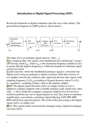
 (Image space)")


")