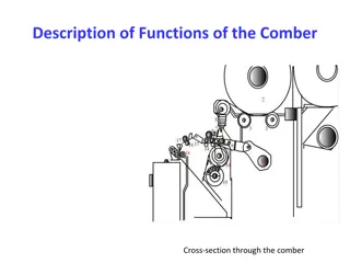
Sliver Formation and Processing in Comber Machines
Formation and processing of sliver in comber machines involve various stages such as withdrawal of the web, sliver formation, sliver take-off, drafting arrangement, and waste removal. The web is collected and formed into a sliver through a series of rollers, trumpets, and calender rollers. Subsequently, the sliver is guided, compacted, and coiled for further processing. The drafting arrangement allows for adjustable drafting zones, while waste removal is achieved through a rotating brush. Overall, the process ensures the production of high-quality sliver for subsequent textile processing.

Download Presentation

Please find below an Image/Link to download the presentation.
The content on the website is provided AS IS for your information and personal use only. It may not be sold, licensed, or shared on other websites without obtaining consent from the author.If you encounter any issues during the download, it is possible that the publisher has removed the file from their server.
You are allowed to download the files provided on this website for personal or commercial use, subject to the condition that they are used lawfully. All files are the property of their respective owners.
The content on the website is provided AS IS for your information and personal use only. It may not be sold, licensed, or shared on other websites without obtaining consent from the author.
E N D
Presentation Transcript
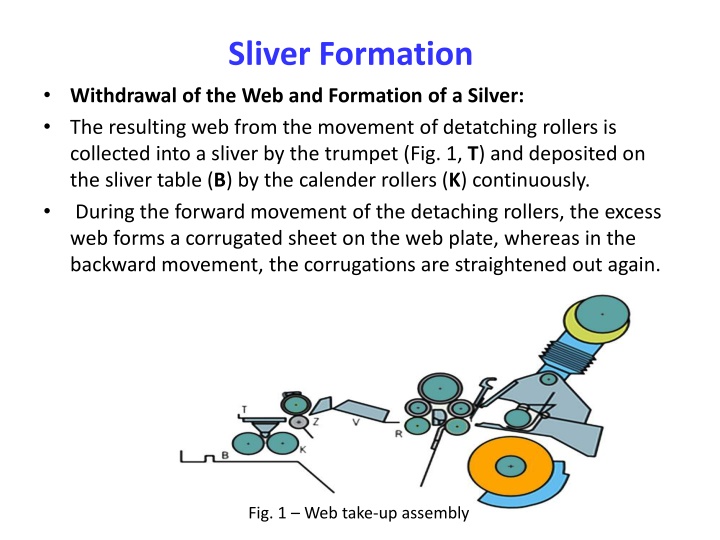
Sliver Formation Withdrawal of the Web and Formation of a Silver: The resulting web from the movement of detatching rollers is collected into a sliver by the trumpet (Fig. 1, T) and deposited on the sliver table (B) by the calender rollers (K) continuously. During the forward movement of the detaching rollers, the excess web forms a corrugated sheet on the web plate, whereas in the backward movement, the corrugations are straightened out again. Fig. 1 Web take-up assembly
The web plate therefore functions as a web reserve zone. Collection of the web is also done at the web plate or in the zone immediately following it. The web is collected towards the center line (Fig. 2, a), as in older web pans, or in one side (b) of the web plate as in modern combers. With a central collecting action, the slightly thicker piecing lines are formed into curves, which distinctly emphasizes the combing cycles (piecing waves). If the web is collected to one side (Fig. 2, b), the piecing lines form diagonals, resulting in partial compensation of the piecing waves. Fig. 2 Removal of the web
Sliver Take-Off After the sliver formation, it is pulled together from combing heads on the sliver table where it takes 90 deflection pin (Fig. 3, P) and are drawn to form a single sliver from the table (Fig. 4, B) by the drafting arrangement (S) which placed at the end of machine. Many manufacturers provide deflector pins that are adjustable or can be rotated eccentrically by minimal amounts. Piecings of the individual slivers can be shifted relative to each other which results in partial compensation (suppression) of the combing piecings. Fig. 3 Sliver formation
Drafting Arrangement In the Rieter comber, the sliver table is drafted by means of vertically inclined 3-over-3 drafting arrangement (Fig. 5), sometimes with an additional pressure bar in the main draft zone. It has two drafting zones namely break draft as well as main draft and the distances between pair of rollers and the amounts of draft are adjustable. The overall draft obtained by this drafting system lies between 9 and 16. At the delivery end of the drafting arrangement a trumpet collects the discharged web and guides it, with additional compacting, to the delivery rollers. Fig. 5 The drafting system of combers
In order to guide this combed sliver, rieter machine provides narrow conveyor belt F. Two stepped discs (S) are located above the rotary table (D) to compact the sliver, Compacting step also increases the inherent coherence of the sliver. Stepped also acts as a measuring device for the hank of the sliver. The sliver formed in this way is coiled cycloidically. The coiler comprises a rapidly rotating table (D) and a slowly rotating can turntable below. Fig. 6 Sketch of the drafting system of the combers Fig. 7 Coiling of sliver
Waste Removal In order to remove eliminated material a rapidly rotating brush is mounted below the comb-carrying cylinder (Fig. 8). This removal occurs when the half- lap comb engages with the brush, which then ejects the noil into a duct forming part of a suction system. This leads to a filter drum behind the machine to a fiber separator (Fig. 9) within the machine, or to a central waste removal system (Fig. 10). Modern combers uses the feature called slow cycle that is precisely adjustable, used to adjust pre-set intervals, the movements of the machine parts and they are slowed down to 1/5 of normal speed which help the brushes to continue to rotate at full speed, thus subjecting the circular combs to produce intensive cleaning effect Fig. 8 Stripping circular combs
Fig. 9 Removal of waste using a fiber separator Fig. 10 Central waste removal