The Functions of a Comber: Cross-section Overview

Explore the detailed functions of a comber through a cross-section view. Learn about the process of feeding the material in the form of a lap, combing out fibers, maintaining constant tension, and creating slivers. Discover the role of eccentric shafts, nippers, combing segments, detaching rollers, and more in the combing operation.

Download Presentation

Please find below an Image/Link to download the presentation.
The content on the website is provided AS IS for your information and personal use only. It may not be sold, licensed, or shared on other websites without obtaining consent from the author.If you encounter any issues during the download, it is possible that the publisher has removed the file from their server.
You are allowed to download the files provided on this website for personal or commercial use, subject to the condition that they are used lawfully. All files are the property of their respective owners.
The content on the website is provided AS IS for your information and personal use only. It may not be sold, licensed, or shared on other websites without obtaining consent from the author.
E N D
Presentation Transcript
Description of Functions of the Comber Cross-section through the comber
The material is fed in the form of lap which rests on two support rolls (3), on which it slowly unrolls also. The web passes over an eccentric shaft (4) acting as a diverter. This serves to keep web tension constant during the forward and return movements of the nippers. Forward movement of the web into the nippers is performed by feed roller (5) and is carried out in very small steps (around 5 mm). When feed has been completed, the nippers (Fig. 2) are closed by allowing spring (8) to press nipper plate (7) against the cushion plate. During the return swing of the nippers, caused by the oscillation of nipper shaft (13), the nipped web is presented to combing segment (10) mounted on rotating cylinder (11) and is combed out. The nippers swing forward again to enable the tuft to be detached from the fiber fringe by rotating detaching rollers (14), which are mounted as a stationary unit.
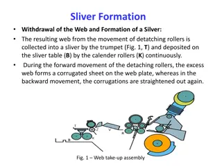
Since the trailing part of the fiber fringe is clamped inside the nippers, no combing can be carried out in this zone, the rear end of the fiber fringe has to be combed through another device, it may be needles or teeth of top comb (9), in order to complete the combing operation. In order to clean the circular comb, a brush (19) is provided over the comb. The web created by piecing at detaching rollers (14) now passes to a web plate (15) and then via lead-off rollers (16) to the trumpet (17), forming the sliver. Thereafter, table rollers (18) guide the sliver formed in this way to the transverse table, on which all eight slivers are combined, drafted and delivered as single sliver by drafting arrangement. After the material has been drawn out in this device to a single sliver, it is then coiled in a can.
Feed of the Lap Sheet Two fluted rollers, driven at constant speed, unroll the web from lap (2). An eccentric shaft (4) is fitted between the rollers and feed cylinder (5). The web is fed over this shaft, which is rotated intermittently in time with the nipper cycle. Each shaft rotation represents less than a full revolution, gives a forward direction initially and then backward rotation This back-and-forth rotation ensures uniform tension in the web and hence prevents false drafts, which could otherwise arise as a result of fluttering of the web as the distance between the stationary rollers and the feed rollers increases and decreases with the backward and forward movement of the nippers. The eccentricity of the shaft compensates for these changes in distance.
The Feed Device There is no machine drive of the feed rollers as such; they are driven indirectly by the opening and closing of the nipper plates. . Settings:Forward shift of the web by the feed roller into the opened nippers can be performed: while the nippers move forward (described above as forward feed); or When the nippers swing back (described as backward feed). Some types of comber can be operated in only one feed mode (forward feed), others can be operated selectively in either mode. Selection of the required mode then involves an adjustment. On the comber this can be carried out quickly and easily by replacement of the two drive change gears on opposite sides of the feed roller (Fig. 3). Rotation of the feed rollers to feed the lap sheet forward by 4.3 to 6.7 mm is derived from the relative movements of the upper and lower nippers. For example, in the case of forward feed, when the upper nipper plate is opened it rotates the roller via the ratchet (by one ratchet tooth) by withdrawing the pawl secured to the upper nipper plate. Whereas in backward feed, i.e. rotation of the cylinder as the nippers close, a pair of gear wheels and an internally toothed ratchet are needed. The change wheels can be replaced to adjust the type of feed and the feed amount per cycle.
Feed distances per cycle used in the comber Feed Distance per cycle (mm) Type of Feed No. of Teeth on the Ratchet Forward Feed 14 6.7 16 5.9 18 5.2 Backward Feed 16 5.9 18 5.2 20 4.7 22 4.2 Arrangement of the nipper, the feeding and the detaching device Feed roller drive
The construction of the nipper assembly Fig 5: The form of the nipper bite Fig 6The nipper support Fig 4: The nipper suspension
The nipper assembly (Fig. 4) is of enormous importance to the design of a comber. The mass of the nippers should be chosen carefully because it is accelerated and decelerated back to rest twice per nipper cycle (up to 7 times per second in modern machines). A low-mass nipper assembly for example, made of aluminum alloy is therefore advantageous. At the same time it should also clamp a relatively thick lap batt (up to 80 ktex) firmly and evenly. Therefore nipper plates must be made of steel (at least the clamping region), and the upper plate must be stiff while the lower plate may slightly springy. The upper nipper is mounted so that it can pivot on the lower nipper on pivot axis (a), and can therefore be raised and lowered. Two springs (8), one each to right and left of the nipper assembly, generate the required contact pressure for the nipper closing.
The so-called bite must have a special form, as illustrated in Fig.5. The nose (n) is designed to press the fiber fringe downward during clamping, so that the fringe cannot escape the action of the circular combs. In combing process, detaching distance also place important role..In old combers the distance between the feed rollers, within the nipper plates and the detaching rollers (in their nearest position) was too wide, (strictly speaking the distance between the feed roller and the nipper mouth) . resulted in slightly uncontrolled fiber extraction during the combing and detaching operation. Solved this problem in a simple way by shifting the feed roller closer to the nipper mouth, and improving web guidance within the nipper installation by means of a special guide plate (Fig. 6) at the feed roller. This arrangement saves quite a considerable amount of good fibers.
The Nipper Movements The lower nipper plate (Fig.7, 5) is supported at the front by two pivot levers (6), on the left and right respectively, pivoted on comb axis (7) of the circular combs, and also by two swing arms (2) screwed onto nipper shaft (1) and rotatable at point 8. During rotation of the nipper shaft which is less than a full revolution in the course of each combing cycle, the whole nipper assembly is moved back and forth about point (8) by swing arm (2).
Forth means the nippers are moved closer to the detaching rollers as far as the position of closest approach (the detachment setting), and then withdrawn again. The upper nipper is movably supported on the lower nipper at point 10, and is also suspended from shaft (12) by means of spring (11). Therefore, as the nipper assembly is moved forward, the upper nipper is raised relative to the lower nipper owing to the different lengths (different leverage) of the lever mechanism, and the nippers are opened. As the nippers are withdrawn, spring (11) presses the upper nipper back against the lower nipper (due to the different length of the levers) Movement of the nippers should be monitored as they are not closed suddenly and sharply, but gently pressed together with gradually increasing pressure. This gentle closure of the nippers is effected by an eccentric (12). During continuous rotation of the eccentric, the spring is periodically compressed and then released
Hanging and Standing Pendulum The nippers are arranged either on a crank beneath the bottom nipper plate (standing pendulum) moving forward and backward, or they are hanging on a pivot above the top nipper plate for the forward and backward movement. The arrangement one way or the other has a major influence on combing performance. With a standing pendulum (Fig.9) the nippers, together with the batt to be combed, move concentrically with the circular comb. The distances to the clothing of the circular comb show little difference (almost constant treatment of the fringe). With a hanging pendulum (b) the variation of distances is larger, and the lowest and highest points of contact also vary, depending on settings. This results in an unfavorable combing operation.
A cylinder drive shaft (Fig. 8, R) extends through the whole machine, and carries one combing cylinder (D) per combing head. The combing cylinder in turn supports a combing segment (half-lap) (S), which is bolted to the cylinder and is fitted with metallic clothing (K). Only metallic clothing is now used on high-performance combers, since clothing is more robust than the needles that were used formerly, needs no maintenance, is not liable to damage in use, and permits operation with a thick batt sheet. Nowadays metallic clothing is available with different point densities as many as three to five zones of point density, i.e. with fewer teeth at the start, a somewhat higher density in the central zone and a still higher density in the trailing zone.
The Top Comb The replaceable top comb is arranged between nippers (Z) and detaching rollers (A) The top combcomprises a holder (Fig. 10, H) to which needle bar (B) is secured by screws. The needle bar consist of set of needles which are soldered over the bar. The holder mounts the top comb on the lower nipper plate so that the top comb swings with that plate. The needles have a flattened cross-section and a bend. Apart from its participation in the swinging movements of the nippers, the top comb is fixed. During detaching the fiber fringe is pressed into the needles of the comb automatically. The spacing from the detaching rollers plays major role which is also to be adjustable The top comb assembly The top comb
The Operation of the Combs The circular combs can treat only the forward portion of the fiber fringe to be processed, since the comb clothing do not penetrate exactly to the bite of the nippers and also because the rear ends of the fibers are located within the nippers. The fairly long, trailing portion has therefore to be combed out by another device called the top comb while being drawn through it (a passive process). This could lead to the false impression that the trailing portion of the fringe is not processed as effectively as the front portion, because it is not passed through a complete combing zone (circular combs), but only through a single row of needles. In fact, the quality of processing of both portions is the same. This statement requires some explanation. Cleaning and elimination of short fibers is, of course, performed by the top comb, but also at the same time by the retaining effect (self- cleaning effect) of the batt in the nippers.
During detaching less than 20% of the fibers in the nippers are pulled out of the batt (Fig.11). This low percentage of fibers is unable to take the impurities within the batt with it, because the retaining force of the more than 80% of fibers of the thick batt that remain is too strong. Impurities, neps, and short fibers therefore remain in the sheet as the other fibers are detached. It goes without saying that this retained material also has to be eliminated somehow, somewhere. It occurs when the fringe is treated by the circular comb during the next combing cycle, or the following one. So that elimination of impurities is always performed by the circular comb. The self-cleaning effect can be influenced by several factors, including the batt weight and the degree of parallelization of the fibers. Of course, the self- cleaning effect is better, the lower the parallelization of the fibers and the more voluminous the batt. Unfortunately, however, the latter entails overloading of the combs and very poor combing performance. As usual in spinning, the golden mean has to be found.
Piecing Fig. 12 Eccentric withdrawal of the web from the web plate Fig. 13 The back-and-forth movement of the detaching rollers
After the operation of the circular combs the detaching rollers feedback the part of previously formed web. The nippers swing forward and lay the fiber tuft that has just been combed onto the portion of the web projecting from the detaching rollers. When the detaching rollers now rotate again in the web take-off direction, they draw the fiber tuft that is immediately combed through the top comb and out of the fringe. The coherent web at the detaching rollers is thus lengthened by a new web strip. As a result of this operation the newly formed coherent web consists of small fiber tufts laid on top of each other in the same way as roofing tiles. The subsequently formed sliver still contains these periodic irregularities, a distinct source of faults in the operation of rectilinear combers.
The sliver produced in this way will have wave-like structure with periodic variations. These variations are visible in the spectrogram in the form of peaks for every combing cycles (at about 30 - 75 cm). Both the spinning mill and the machine designer must strive to keep this irregularity as low as possible. The designer therefore employs eccentric withdrawal of the web from the web plate (Fig. 12) which reduces the irregularity. The spinning mill can influence this via the machine settings. The fiber tufts drawn off by the detaching rollers can be compared with very flat parallelograms, although normally the leading edge is blunter than the trailing edge. By using correct machine settings it is possible to lay these parallelograms on each other in such a way that any unevenness is partly canceled out. On the other hand, incorrect setting will cause an increase in unevenness. In order to carry out the piecing operation, the detaching rollers must perform a back-and- forth movement (Fig. 13) in which the forward component (V) is larger than the backward component (R), so that effective take-off (T) is achieved. In modern combers backward movement amounts to about 60% of the forward movement. The back-and-forth movement of the detaching rollers derives from a differential gear. An intermittent rotation (Fig. 14, A) is superimposed upon a constant basic rotation (B) generated by the comb shaft. The intermittent rotation is somewhat faster than the basic rotation. If these rotations are acting in the same direction (A + B), the result is a rapid acceleration of the detaching rollers in the forward direction (detaching operation) (Fig. 14, left).


 is of enormous importance")


 extends through the")