Sequence Generators in Digital Circuits
Explore the concept of sequence generators in digital circuits, focusing on PN sequence lengths, feedback taps, XOR gates, and designing patterns with examples and visual aids, including Karnaugh maps.

Download Presentation

Please find below an Image/Link to download the presentation.
The content on the website is provided AS IS for your information and personal use only. It may not be sold, licensed, or shared on other websites without obtaining consent from the author.If you encounter any issues during the download, it is possible that the publisher has removed the file from their server.
You are allowed to download the files provided on this website for personal or commercial use, subject to the condition that they are used lawfully. All files are the property of their respective owners.
The content on the website is provided AS IS for your information and personal use only. It may not be sold, licensed, or shared on other websites without obtaining consent from the author.
E N D
Presentation Transcript
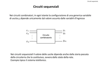
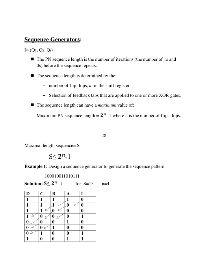
Sequence Generators: I= (Q1, Q2, Qi) The PN sequence length is the number of iterations (the number of 1s and 0s) before the sequence repeats. The sequence length is determined by the: number of flip flops, n, in the shift register Selection of feedback taps that are applied to one or more XOR gates. The sequence length can have a maximum value of: Maximum PN sequence length = ??- 1 where n is the number of flip- flops. 28 Maximal length sequence= S S ??-1 Example 1: Design a sequence generator to generate the sequence pattern 100010011010111 Solution: S ??-1 for S=15 n=4 D 1 1 1 1 0 0 0 1 A 1 0 0 0 1 0 0 1 C 1 1 1 0 0 0 1 0 B 1 1 0 0 0 1 0 0 I 0 0 0 1 0 0 1 1
0 0 1 1 0 1 0 0 1 1 0 1 0 1 0 1 0 1 1 1 1 1 1 0 1 0 1 1 1 0 1 0 1 1 1 I = ?D + C? = C D 29
Note: When the feedback logic include any XOR gates the resulting circuit it called (Linear PN) otherwise it's called (non Linear PN). H.W: Design a sequence generator to generate the sequence pattern: 111101011001000 Example 2: Design a sequence generator to the prescribed sequence 1011110. Solution: S ??- 1 S =7 n=3 30 D 1 1 C 1 0 B 0 1 A 1 0 I 0 1
0 1 0 1 1 1 0 1 1 1 0 1 1 1 1 1 1 1 1 0 1 1 1 0 1 Note: If there is similar states we need to add another stage to remove similarity. AB 00 01 11 10 CD X X 1 1 X X 1 0 1 X X 0 1 00 X X X 01 11 10 ? = ? + ? + ? I =A.C.D 31
Note: The Karnaugh map for five variables will be as shown in the figure below: