RTC Experiments with DS1307 for Arduino
Delve into the world of real-time clock (RTC) experiments using the DS1307 serial real-time clock with this comprehensive guide. Learn how to write to and read from the RTC, set up the board with Arduino, utilize interrupts for RTC reading, and more through step-by-step instructions and insightful visuals.

Download Presentation

Please find below an Image/Link to download the presentation.
The content on the website is provided AS IS for your information and personal use only. It may not be sold, licensed, or shared on other websites without obtaining consent from the author.If you encounter any issues during the download, it is possible that the publisher has removed the file from their server.
You are allowed to download the files provided on this website for personal or commercial use, subject to the condition that they are used lawfully. All files are the property of their respective owners.
The content on the website is provided AS IS for your information and personal use only. It may not be sold, licensed, or shared on other websites without obtaining consent from the author.
E N D
Presentation Transcript
RTC experiment Prabhas Chongstitvatana
DS1307 The DS1307 serial real-time clock (RTC) is a lowpower, full binary-coded decimal (BCD) clock/calendar
to write to RTC control byte DS1307 1101000X 1 start condition 2 send control byte write 3 send address 4 send data 5 send another data or stop condition
to read from RTC 1 start condition 2 send control byte read 3 send address 4 start condition 5 send control byte 6 read first byte 7 read another byte or stop condition
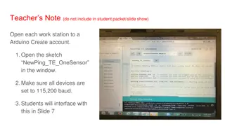
polling Master (Arduino) 1 setup RTC 2 main loop 2.1 read clock 2.2 print time 2.3 wait 1 second
Read RTC with interrupt Using interrupt Master 1 Setup RTC with square wave out at pin INT (use CTRL = 0x10) 2 We get interrupt signal from RTC (pin INT) to Arduino pin digital-2 3 Attach interrupt service routine 4 in ISR if interrupt occurs set int_status 5 Main loop 5.1 Wait for interrupt by checking int_status 5.2 Then read clock 5.3 Print time 5.4 Reset int_status
Setting up the board DS1307 Atmega +vcc +5v INT digital-2 SDA analog-4 SCL analog-5 GND GND
Set Int0 pin 1. The pin PD2, digital-2 on Atmega is connected to Int0 (interrupt 0) and is pull-up by a resistor and connected to a push switch. 2. To connect the output INT of DS1307 to Atmega you must open the jumper (2).
Important notice You have to detach the wire to pin digital-2 before upload program to Atmega and reattach it later. Otherwise it will interfere with the upload process as the pin PD2 is the actual interrupt pin, the previous state of INT of DS1307 board will affect it.
Set control register of DS1307 Set bit 7 (OUT) to 0 Set bit 4 (SQWE) to 1 Set bit 1, bit 0 (RS1,RS0) to 00 = output square wave 1 Hz to pin INT of board DS1307
program #include <Wire.h> int ledp = 13; int intp = 2; // dig port int0:PD2 (dig-2) volatile boolean ledst = LOW; volatile boolean intst = LOW; ... void setup(){ pinMode(ledp,OUTPUT); pinMode(intp,INPUT); 1 You need to send the correct control value. sec = 0x55; xmin = 0x59; hour = 0x23; ... ctrl = 0x10; <<<<-------------- (1) SetClock(); attachInterrupt(0,RTCint, CHANGE); <<< ---- (2) } 2 To set up interrupt service routine, RTCint is attached to int0 and trigger by change (which is a 1 Hz square wave from DS1307 void RTCint(){ if(digitalRead(intp) == LOW){ intst = HIGH; // set interrupt status digitalWrite(ledp,HIGH); }else digitalWrite(ledp,LOW); } void loop(){ while(intst == 0) // wait for interrupt GetClock(); printhex(hour); ... intst = 0; // reset int status }