Rectangular Waveguides and Cutoff Frequency

Waveguides
•
Rectangular Waveguides
–
TEM, TE and TM waves
–
Cutoff Frequency
–
Wave Propagation
–
Wave Velocity,

Waveguides
•
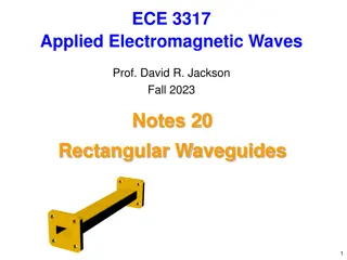
In the previous chapters, a pair of
conductors was used to guide
electromagnetic wave propagation.
This propagation was via the
transverse electromagnetic (TEM)
mode, meaning both the electric and
magnetic field components were
transverse, or perpendicular, to the
direction of propagation.
•
In this chapter we investigate wave-
guiding structures that support
propagation in non-TEM modes,
namely in the transverse electric (TE)
and transverse magnetic (TM) modes.
•
In general, the term waveguide refers
to constructs that only support non-
TEM mode propagation. Such
constructs share an important trait:
they are unable to support wave
propagation below a certain frequency,
termed the
cutoff frequency
.
Rectangular
waveguide
Circular
waveguide
Optical Fiber
Dielectric Waveguide
Rectangular Waveguide
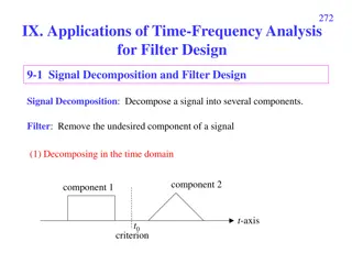
Location of modes
•
Let us consider a rectangular waveguide
with interior dimensions are a x b,
•
Waveguide can support TE and TM modes.
–
In TE modes, the electric field is transverse
to the direction of propagation.
–
In TM modes, the magnetic field that is
transverse and an electric field component is
in the propagation direction.
•
The order of the mode refers to the field
configuration in the guide, and is given by m
and n integer subscripts, TE
mn
and TM
mn.
–
The m subscript corresponds to the number
of half-wave variations of the field in the x
direction, and
–
The n subscript is the number of half-wave
variations in the y direction.
•
A particular mode is only supported above
its cutoff frequency. The cutoff frequency is
given by
Rectangular Waveguide
T
a
b
l
e
7
.
1
:
S
o
m
e
S
t
a
n
d
a
r
d
R
e
c
t
a
n
g
u
l
a
r
W
a
v
e
g
u
i
d
e
Location of modes
Rectangular Waveguide
Rectangular Waveguide
The cutoff frequency is given by
To understand the concept of cutoff frequency, you can use the analogy of a road
system with lanes having different speed limits.
Rectangular Waveguide
Rectangular Waveguide
•
Let us take a look at the field pattern for two
modes, TE
10
and TE
20
–
In both cases, E only varies in the x direction;
since n = 0, it is constant in the y direction.
–
For TE
10
, the electric field has a half sine
wave pattern, while for TE
20
a full sine wave
pattern is observed.
Rectangular Waveguide
Example
Let us calculate the cutoff frequency for the first four modes of WR284 waveguide.
From Table 7.1 the guide dimensions are a = 2.840 mils and b = 1.340 mils.
Converting to metric units we have a = 7.214 cm and b = 3.404 cm.
TE
10
:
TE
01
:
TE
20
:
TE
11
:
TE
10
TE
01
TE
20
TE
11
TM
11
For more detail contact us
Investigate waveguides supporting non-TEM modes like TE and TM, where cutoff frequency is crucial. Rectangular waveguides with TE and TM modes are explored, detailing mode orders and field configurations. The cutoff frequency formula and standard waveguide designations are also discussed, along with an analogy using road lanes. Field patterns for TE10 and TE20 modes are examined, emphasizing the variations in electric field direction. Gain insights into how waveguide designs impact wave propagation characteristics.

Download Presentation

Please find below an Image/Link to download the presentation.
The content on the website is provided AS IS for your information and personal use only. It may not be sold, licensed, or shared on other websites without obtaining consent from the author.If you encounter any issues during the download, it is possible that the publisher has removed the file from their server.
You are allowed to download the files provided on this website for personal or commercial use, subject to the condition that they are used lawfully. All files are the property of their respective owners.
The content on the website is provided AS IS for your information and personal use only. It may not be sold, licensed, or shared on other websites without obtaining consent from the author.
E N D
Presentation Transcript
Waveguides Rectangular Waveguides TEM, TE and TM waves Cutoff Frequency Wave Propagation Wave Velocity, Visit for more Learning Resources Visit for more Learning Resources
Waveguides Circular waveguide Rectangular waveguide In the previous chapters, a pair of conductors was used to guide electromagnetic wave propagation. This propagation was via the transverse electromagnetic (TEM) mode, meaning both the electric and magnetic field components were transverse, or perpendicular, to the direction of propagation. In this chapter we investigate wave- guiding structures that support propagation in non-TEM modes, namely in the transverse electric (TE) and transverse magnetic (TM) modes. In general, the term waveguide refers to constructs that only support non- TEM mode propagation. Such constructs share an important trait: they are unable to support wave propagation below a certain frequency, termed the cutoff frequency. Optical Fiber Dielectric Waveguide
Rectangular Waveguide Let us consider a rectangular waveguide with interior dimensions are a x b, Waveguide can support TE and TM modes. In TE modes, the electric field is transverse to the direction of propagation. In TM modes, the magnetic field that is transverse and an electric field component is in the propagation direction. The order of the mode refers to the field configuration in the guide, and is given by m and n integer subscripts, TEmn and TMmn. The m subscript corresponds to the number of half-wave variations of the field in the x direction, and The n subscript is the number of half-wave variations in the y direction. A particular mode is only supported above its cutoff frequency. The cutoff frequency is given by Rectangular Waveguide Location of modes 2 2 2 2 1 m a n b c m a n b = = + + f mn c 2 2 r r 1 1 1 1 c = = = = u 3 10 m/s c = 8 where o r o r o o r r r r
Rectangular Waveguide The cutoff frequency is given by Rectangular Waveguide = = For air and 1 r 1 r 2 2 c m a n b 2 2 c m a n b = + f = + f mn c 2 mn c 2 r r 3 10 m/s c= 8 where Location of modes Table 7.1: Some Standard Rectangular Waveguide Waveguide Designation WR975 WR650 WR430 WR284 WR187 WR137 WR90 WR62 a b t fc10 (GHz) .605 .908 1.375 2.08 3.16 4.29 6.56 9.49 freq range (GHz) .75 1.12 1.12 1.70 1.70 2.60 2.60 3.95 3.95 5.85 5.85 8.20 8.2 12.4 12.4 - 18 (in) 9.750 6.500 4.300 2.84 1.872 1.372 .900 .622 (in) 4.875 3.250 2.150 1.34 .872 .622 .450 .311 (in) .125 .080 .080 .080 .064 .064 .050 .040
To understand the concept of cutoff frequency, you can use the analogy of a road system with lanes having different speed limits.
Rectangular Waveguide Rectangular Waveguide Let us take a look at the field pattern for two modes, TE10 and TE20 In both cases, E only varies in the x direction; since n = 0, it is constant in the y direction. For TE10, the electric field has a half sine wave pattern, while for TE20 a full sine wave pattern is observed.
Rectangular Waveguide Example Let us calculate the cutoff frequency for the first four modes of WR284 waveguide. From Table 7.1 the guide dimensions are a = 2.840 mils and b = 1.340 mils. Converting to metric units we have a = 7.214 cm and b = 3.404 cm. 2 2 c m a n b 3 10 m/s c = = + 8 where f mn c 2 TM11 m 8 3 10 x 100 1 c cm m s TE10: = = = 2.08 GHz f TE10 TE20 TE01 TE11 ( ) 10 c 2 2 7.214 a cm m 2.08 GHz 4.16 GHz 4.41 GHz 4.87 GHz 8 3 10 x 100 1 c cm m s TE01: = = = 4.41 GHz f ( ) 01 c 2 2 3.404 b cm c a x TE20: = = 4.16 GHz f 20 c m 8 3 10 2 2 1 1 100 1 cm m s TE11: = + = 4.87 GHz f 11 c 2 7.214 3.404 cm cm For more detail contact us For more detail contact us