Frequency Response in Passive Filters
Frequency response in passive filters plays a crucial role in signal processing by selectively allowing or blocking specific frequencies. This article explores the concept of passive filters, including lowpass, highpass, bandpass, and bandstop filters, their characteristics, and how they can be implemented using RL and RC circuits. Different transfer functions and cutoff frequencies are discussed, shedding light on designing and analyzing frequency-selective circuits.

Download Presentation

Please find below an Image/Link to download the presentation.
The content on the website is provided AS IS for your information and personal use only. It may not be sold, licensed, or shared on other websites without obtaining consent from the author.If you encounter any issues during the download, it is possible that the publisher has removed the file from their server.
You are allowed to download the files provided on this website for personal or commercial use, subject to the condition that they are used lawfully. All files are the property of their respective owners.
The content on the website is provided AS IS for your information and personal use only. It may not be sold, licensed, or shared on other websites without obtaining consent from the author.
E N D
Presentation Transcript
Linear Circuit Analysis 2 Lecture 8 Dr.-Ing. Erwin Sitompul President University http://zitompul.wordpress.com 2 0 1 9 President University Erwin Sitompul LCA2 7/1
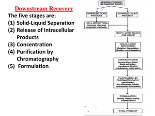
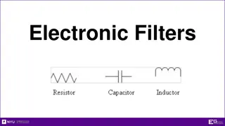
Chapter 14 Frequency Response Passive Filters As a frequency-selective device, a filter can be used to limit the frequency spectrum of a signal to some specified band of frequencies. A filter is a passive filter if it consists of only passive elements R, L, and C. A filter is an active filter if it consists of active elements (such as transistors and op amps) in addition to passive elements R, L, C. President University Erwin Sitompul LCA2 8/2
Chapter 14 Frequency Response Passive Filters There are four types of filters based on the frequencies they pass or reject: 1. Lowpass filter, passes low frequencies and rejects high frequencies. 2. Highpass filter, passes high frequencies and rejects low frequencies. 3. Bandpass filter, passes frequencies within a frequency band and blocks frequencies outside the band. 4. Bandstop filter, passes frequencies outside a frequency band and blocks frequencies within the band. 1. 2. 3. 4. President University Erwin Sitompul LCA2 8/3
Chapter 14 Frequency Response Passive Filters President University Erwin Sitompul LCA2 8/4
Chapter 14 Frequency Response Passive Filters A typical lowpass filter is formed when the output of an RC circuit is taken off the capacitor. The transfer function is Note that The half-power frequency, or the cutoff frequency c, is obtained by setting the magnitude of H( ) equal to 1/ 2. President University Erwin Sitompul LCA2 8/5
Chapter 14 Frequency Response Passive Filters The cutoff frequency ccan be found by through A lowpass filter can also be formed when the output of an RL circuit is taken off the resistor. Of course, there are many other circuits for lowpass filter. Find the transfer function of lowpass RL filter. President University Erwin Sitompul LCA2 8/6
Chapter 14 Frequency Response Passive Filters A highpass filter is formed when the output of an RC circuit is taken off the resistor. The transfer function is Note that The cutoff frequency is A highpass filter can also be formed when the output of an RL circuit is taken off the inductor. Find the transfer function of highpass RL filter. President University Erwin Sitompul LCA2 8/7
Chapter 14 Frequency Response Passive Filters A bandpass filter is formed when the output of an RLC circuit is taken off the resistor. The transfer function is Note that The bandpass filter passes a band frequencies 1< < 2. 0is the center frequency, which is equal to the resonant frequency. What is resonant frequency? President University Erwin Sitompul LCA2 8/8
Chapter 14 Frequency Response Passive Filters Now we derive how to find the cutoff frequencies 1 and 2from the transfer function of R L ( ) = H + ( 1 ) R j C At cutoff frequency, the magnitude of the transfer function is 1/ 2. 1 R L = + ( 1 ) R j C 2 + = ( 1 ) 2 R j L C R 2 ( 1 R ) L C = 1 + = 2 2 ( 1 ) 2 R L C R 2 = 2 2 ( 1 ) L C R 2 ( 1 R ) L C + = 2 2 2 R R R 2 = ( 1 ) R L C 2 ( 1 R ) L C + = 1 2 R R 2 President University Erwin Sitompul LCA2 8/9
Chapter 14 Frequency Response Passive Filters = = + ( 1 ) R L C ( 1 ) R L C + = = 2 2 1 0 1 0 LC RC LC RC + + 2 2 2 2 4 4 RC R C LC R LC RC R C LC R L LC = = 2 2 2 2 1 R L 1 R L = + = + 2 2 LC 2 2 L LC 2 2 1 R L R L 1 R L R L = + + = + + 2 1 2 2 LC 2 2 LC We solve 2 quadratic equations, each with 2 solutions. There are in total 4 solutions of but 2 of them are negative and not possible solution (not physical). President University Erwin Sitompul LCA2 8/10
Chapter 14 Frequency Response Passive Filters 2 1 R L R L = + + 1 2 2 LC Low cutoff frequency 2 1 R L R L = + + 2 2 2 LC High cutoff frequency R L = 2 1 Bandwidth Resonant frequency President University Erwin Sitompul LCA2 8/11
Chapter 14 Frequency Response Passive Filters A bandpass filter can also be formed by cascading a lowpass filter with 2= cwith a highpass filter 1= c. Write the transfer function of this kind of bandpass filter. President University Erwin Sitompul LCA2 8/12
Chapter 14 Frequency Response Passive Filters A filter that prevents a band of frequencies between two designated values from passing is variably known as a bandstop, bandreject, or notch filter. A bandstop filter is formed when the output of an RLC circuit is taken off the LC series. The transfer function is Note that President University Erwin Sitompul LCA2 8/13
Chapter 14 Frequency Response Passive Filters The bandstop filter passes a band frequencies < 1and > 2. 0is the center frequency, which is equal to the resonant frequency. The cutoff frequencies are The resonant frequency and the cutoff frequencies for bandpass filter and bandstop filter are identical. President University Erwin Sitompul LCA2 8/14
Chapter 14 Frequency Response Passive Filters Several conclusions regarding passive filters: 1. The maximum gain of a passive filter is unity (one). To generate a gain greatre than unity, we should use an active filter. 2. There are other ways to get the types of filters discussed until now, while only using passive elements of R, L, and C. 3. The filters discussed until now are the simple types. Many other filters have sharper and complex frequency response. President University Erwin Sitompul LCA2 8/15
Chapter 14 Frequency Response Example 1 President University Erwin Sitompul LCA2 8/16
Chapter 14 Frequency Response Example 1 President University Erwin Sitompul LCA2 8/17
Chapter 14 Frequency Response Example 1 President University Erwin Sitompul LCA2 8/18
Chapter 14 Frequency Response Practice Problem President University Erwin Sitompul LCA2 8/19
Chapter 14 Frequency Response Example 2 R L 150 L = = Bandwidth 2 1 150 0.2387 H = = 2 100 L 2 100 = = = Resonant frequency 1 LC 0 1 = = 2 200 1 0.2387C C 2 (0.2387)(2 2.653 F 200) = What is 1and 2? President University Erwin Sitompul LCA2 8/20
Chapter 14 Frequency Response Practice Problem President University Erwin Sitompul LCA2 8/21
Chapter 14 Frequency Response Homework 8 1. (05.RBY+11.AMS 9) 2. (Oct.05.20.23) Deadline: Wednesday, 10 April 2019. President University Erwin Sitompul LCA2 8/22