Radiation from Aperture in Cylinder
This text discusses the radiation from an aperture in a cylinder, exploring mathematical equations and transformations related to electromagnetic fields. It covers principles of wave propagation using cylindrical transforms, along with calculations and derivations involved in the electromagnetic analysis of the aperture. The content delves into the properties of electromagnetic waves in cylindrical structures, providing insights into the behavior of radiation patterns. It also addresses the use of far-field identities for analyzing antenna performance.
Download Presentation

Please find below an Image/Link to download the presentation.
The content on the website is provided AS IS for your information and personal use only. It may not be sold, licensed, or shared on other websites without obtaining consent from the author. Download presentation by click this link. If you encounter any issues during the download, it is possible that the publisher has removed the file from their server.
E N D
Presentation Transcript
ECE 6341 Spring 2016 Prof. David R. Jackson ECE Dept. Notes 17 1
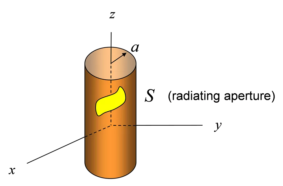
Radiation From Aperture in Cylinder z a = = n integer continuous variable = k z S (radiating aperture) y x 1 ( ) + = jk z (2) n jn ( ) f k A e H k e dk z z n z z 2 = n 1 ( ) + = jk z (2) n jn ( ) F e g k H k e dk z z n z z 2 = n Note: The factor of 2 is added for convenience. 2
Aperture in Cylinder (cont.) From the TMz/TEz Tables: 2 1 = + 2 0 E k A z z 2 j z 0 0 1 2 1 1 A dF d = + E z z z j 0 0 0 2 k Hence, on the aperture we have + 1 1 )( ) ( + ( ) , , = (2) n 2 0 2 z jk z jn ( ) f k H E a z e k a k k e dk z z n z z 2 j = n 0 0 1 1( a ( ) (2) n )( ) ( ) f k H jn jk k a z n z j + 1 + ( ) 0 0 , , = jk z jn E a z e e dk z z 1 2 ( ) = + (2) n n ( ) k g k H k a n z 0 3
Aperture in Cylinder (cont.) First, we ll work with Ez. To simplify the notation, let 1 ( ) k ( ) 2 (2) n ( ) ( ) f k a k H k a n z n z j 0 0 Then + 1 + ( ) , , = jk z jn ( ) E a z e a k e dk z z n z z 2 = n 4
Aperture in Cylinder (cont.) jm 0,2 Multiply by and integrate over e 2 1 + ( ) ( ) , , = jk z jm 2 ( ) E a z e d a k e dk z z m z z 2 0 (from orthogonality, with m = n) Next, divide both sides by 2 : 2 1 1 + ( ) , , = jk z jm ( ) E a z e d a k e dk z z m z z 2 2 0 = 1 ( ) F a k m z 5
Aperture in Cylinder (cont.) Hence 2 1 ( ) = , , jm ( ) a k F E a z e d m z z 2 0 2 1 + ( ) = , , jk z jm E a z e d e dz z z 2 0 Define cylindrical transform : 2 1 ( ) ( ) ( ) + = jk z jm , , , F f z f m k f z e e dzd z c z 2 0 Then = ( ) ( , , E a m k ) a k m z z z 6
Aperture in Cylinder (cont.) Recall that 1 ( ) k ( ) 2 (2) n ( ) ( ) f k a k H k a n z n z j 0 0 Hence ( , , ( k a ) j E a n k = ( ) f k 0 0 2 k H z z n z (2) n ) Similarly, (details omitted) we have nk ak ( ) = ( ) , , a n k ( , , E a n k ) g k E 0 z ( ) n z z z z 2 (2) n k H k a 7
Aperture in Cylinder (cont.) Now use the far-field identity: ( ) ( ) = A F f g k k 1 ( ) + z jk z (2) n n z jn e H k e dk z z 2 = n z n z r ( ( cos ) cos ) f k g k A F jk r + 1 e ( ) 0 0 n + z 1 jn n ~ 2 e j 2 r = n 0 z n As before, j ~ sin E A z 8
Aperture in Cylinder (cont.) Also, from duality, j ~ sin H F z Hence ~ E H 0 sin j F 0 z or k ~ sin 0 E j F z 0 9
Aperture in Cylinder (cont.) Summary k j ~ sin E A ~ sin 0 E j F z z 0 ( ( cos ) cos ) f k g k A F jk r + 1 e ( ) 0 0 n + z 1 jn n ~ 2 e j 2 r = n 0 z n ( , , ( k a ) j E a n k = ( ) f k 0 0 2 k H z z n z (2) n ) nk ak ( ) = ( ) , , a n k ( , , E a n k ) g k E 0 z ( ) n z z z z 2 (2) n k H k a 10
Example z a y = w a A vertical slot is centered at z = 0. S a L y x w V z = 0cos w E x L z E = 0 + 2 1 ( ) ( ) + = , , jk z jn , , a n k E E a z e e dzd z z 2 0 11
Example (cont.) /2 /2 L 1 V w z ( ) = jk z jn , , a n k cos E e d e dz 0 z z 2 L /2 /2 L n k L sin cos z 1 V w 2 2 ( ) = 2 L 0 ( ) 2 n 2 2 k L z 2 Simplifying, we have k L cos z V L n 2 ( ) x x ( ) sin = , , a n k sinc E 0 a ( ) x sinc ( ) z 2 2 2 k L z 12
Example (cont.) From previous analysis: ( , , ( k a ) j E a n k = ( ) f k 0 0 2 z z ( ) 2 n n z ) k H nk ak ( ) = ( ) , , a n k ( , , E a n k ) g k E 0 z ( )( n ) n z z z z 2 2 k H k a Hence, we have = ( ) f k 0 n z ( ( )( n ) ) The field is TEz polarized. , , a n k E 0 = z ( ) g k n z 2 k H k a 13
Example (cont.) Recall that k ~ sin 0 E j F z 0 e jk r + 1 ( ) 0 ( ) + 1 jn n ~ 2 cos F e j g k 0 z n 2 r = n where we now have k L cos ( ( )( n ) ) z , , a n k E VL a n 2 ( ) 0 z = ( ) g k = , , a n k sinc E ( ) n z z 2 2 2 2 k L k H k a z 14
Example (cont.) Hence, after simplifying, we have E = 0 1 2 cos cos k L jk r + 0 1 V L a e n 0 n jn ~ sinc E j e ( ) ( )( n ) 2 2 r 2 2 cos k L sin H k a = n 0 0 Where we have used: ( ) 1/2 = = 2 0 2 z 0sin k k k k = 0cos zk k In far field: 15
Input Impedance y z a WG cavity L y x a L w WG x The slot is assumed to be backed by a cavity, which is a short-circuited length of rectangular waveguide (L w) operating in the TE10 mode. 16
Input Impedance (cont.) z L I WG a ap + V0 - Z Y 0 ap L y -V0 + w Circuit Model Exterior modeling x 1 2 1 2 2 = = * ap * P V I Y V 0 0 s ap sP =complex power radiated into exterior so * 2 V P = s Y ap 2 0 17
Input Impedance (cont.) y L WG Interior modeling ( ) I x WG cavity + V0 - + V(x) - V0 Y + - ap x a Z L 0 WG V WG centerline voltage The voltage on the TL is chosen as the actual voltageat the center of the WG. ( ) ( ) x w = V x E yc 18
Input Impedance (cont.) y L WG Interior modeling I WG cavity + V - + V0 - V0 Y + - ap x a Z L 0 WG V WG centerline voltage To find Z0, equate complex power flows on WG and TL: 2 * 2 E Z w L w L w L E Z V Z 1 2 1 2 1 2 1 2 1 2 z yc TE = = = = y * * z 2 sin VI E H dzdy E dzdy dzdy y y TE L 0 10 10 0 0 0 0 0 0 2 2 E Z 1 2 1 TE L wL V w yc TE = = w 2 4 Z 10 10 19
Input Impedance (cont.) y Interior modeling L WG I WG cavity + V - V0 + V0 - + - x Y ap a L WG Z 0 V WG centerline voltage Hence, we have 2 2 V Z 1 2 1 TE wL V w w L = = TE 2 Z Z or 4 Z 0 10 0 10 where ( ) ( ) 2 = TE / 1 / Z k L 10 0 0 20
Input Impedance (cont.) Exterior modeling of aperture * 2 V P = Y s Aperture admittance: ap 2 0 Hence, we have + 2 2 1 2 = * Y E H adzd ap z 2 V 0 0 where 2 1 = + 2 0 H k F z z 2 j z 0 0 + + 1 1 = 2 (2) n jk z jn ( ) ( ) e k g k H k a e dk z n z z 2 j = n 0 0 21
Input Impedance (cont.) Hence + 2 2 1 2 ( ) = , , * Y E a z ap 2 V 0 0 + 1 1 + jk z 2 (2) n jn ( ) ( ) e k g k H k a e dk adzd z n z z 2 j = n 0 0 Ordering the spatial integrations first, we have + 1 1 a = 2 (2) n ( ) ( ) Y k g k H k a ap n z 2 2 j V = n 0 0 0 + 2 ( ) , , jk z * jn E a z e e dzd dk z z 0 22
Input Impedance (cont.) For the term in brackets, * + + 2 2 ( ) ( ) + , , = , , * jk z jk z jn jn E a z e e dzd E a z e e dzd z z 0 0 ( ) = * 2 , , a n k E z Hence + 1 1 a ( ) 2 n = 2 ( ) ( ) Y k g k H k a ap n z 2 2 j V = n 0 0 0 * k L cos z V L n 2 2 sinc dk 0 a ( ) z 2 2 2 k L z 23
Input Impedance (cont.) Substituting for gn, we have ( ( )( n ) ) , , a n k E = 0 z Recall: ( ) g k n z 2 k H k a + 1 1 a ( ) 2 n = 2 ( ) Y k H k a 0 ap ( ) 2 n 2 2 j V ( ) k H k a = n 0 0 0 * k L k L cos cos z z V L n V L n 2 2 sinc 2 sinc dk 0 a 0 a ( ) ( ) z 2 2 2 2 2 2 k L k L z z 24
Input Impedance (cont.) Simplifying, we have: ( ) 2 n 2 ( ) H k a + a L a = Y k ap ( ) 2 n j ( ) H k a = n 0 2 k L cos z n 2 2 sinc dk z 2 2 2 ( ) k L z 25
Input Impedance (cont.) In normalized form: ( ) 2 n 2 ( ) H k a + k a L a = Y j k 0 ap ( ) 2 n ( ) H k a = n 0 2 k L cos z n 2 2 sinc dk z 2 2 2 ( ) k L z = / k k k 0 z z = / k k k 0 = / dk dk k 0 z z 26
Input Impedance (cont.) The total input admittance seen by the feed is then: = + Y Y Y = 1/ Z Y in stub ap in in ( ) = 10 z 0cot jY Y k L stub WG Note: L The model neglects the effects of higher-order waveguide modes. (This could be accounted for approximately by adding a probe reactance to the input impedance.) WG = Y 1/ Y Z 2 0 0 ap + ( ) ln 0 X k w 0 probe 2 k a 0 probe WG stub w L = TE 2 Z Z 0 10 27
