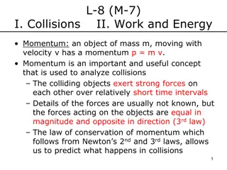
Physics Lab Experiment on Impulse and Collisions
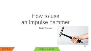
This physics experiment involves measuring force vs. time during the collision of an air track glider with a force transducer to understand impulse. Proper setup of equipment is crucial to obtain accurate data. Through Capstone software, students analyze data to calculate impulse and understand the physics behind collisions.

Download Presentation

Please find below an Image/Link to download the presentation.
The content on the website is provided AS IS for your information and personal use only. It may not be sold, licensed, or shared on other websites without obtaining consent from the author.If you encounter any issues during the download, it is possible that the publisher has removed the file from their server.
You are allowed to download the files provided on this website for personal or commercial use, subject to the condition that they are used lawfully. All files are the property of their respective owners.
The content on the website is provided AS IS for your information and personal use only. It may not be sold, licensed, or shared on other websites without obtaining consent from the author.
E N D
Presentation Transcript
Physics Impulse and Collisions MS&T Physics 1135, Lab O4
Objectives Physics Measure F(t) vs t during the collision of an air track glider with a force transducer and relate this to Impulse. Note: Pay attention to the positioning of your bumpers; they must pass through the photogate unimpeded and hit the force sensor squarely. An impact with the photogate or a glancing blow to the sensor will adversely affect your data. MS&T Physics 1135, Lab O4: Impulse and Collisions Slide 2/6
Apparatus Physics Make sure the bumpers hit the force sensor pad without colliding with the photogate or the force sensor frame or dragging on the air track. Also make sure the flag triggers the photogate and the bumpers do not. MS&T Physics 1135, Lab O4: Impulse and Collisions Slide 3/6
Add Instruments to Capstone Physics Add a Photogate to Digital Input 1 (red). Configure a timer to measure speed. Add a Force Sensor to Analog Input A (green). Press the Tare button on the Force Sensor housing once you have it positioned. Note: There are 3 types of Force Sensor. Use the first, not the economy or student model. MS&T Physics 1135, Lab O4: Impulse and Collisions Slide 4/6
Calculating Areas in Capstone Physics The Highlighter brings up a box that you can drag to highlight specific data. The Area tool displays a numerical approximation to the integral of the selected data, or the whole run if no highlighter is active. These tools can be used independently on each run displayed in the plot. MS&T Physics 1135, Lab O4: Impulse and Collisions Slide 5/6
Finding the Impulse in Capstone Physics Make a table of Time (s) and Speed (m/s) using the data from the photogate. Capstone has no way to tell which direction the glider is going, so it s up to you to keep track of which speeds should be positive and which should be negative. MS&T Physics 1135, Lab O4: Impulse and Collisions Slide 6/6