Parallel Processing and SIMD Architecture Overview
Parallel processors in advanced computer systems utilize multiple processing units connected through an interconnection network. This enables communication via shared memory or message passing methods. Multiprocessors offer increased speed and cost-effectiveness compared to single-processor systems and provide fault tolerance. Current trends show a shift towards clusters of workstations and grid computing. Flynn's Taxonomy categorizes computer architecture based on the flow of instructions and data. SIMD architecture involves a front-end computer connected to a processor array for parallel operations on distributed data.

Download Presentation

Please find below an Image/Link to download the presentation.
The content on the website is provided AS IS for your information and personal use only. It may not be sold, licensed, or shared on other websites without obtaining consent from the author.If you encounter any issues during the download, it is possible that the publisher has removed the file from their server.
You are allowed to download the files provided on this website for personal or commercial use, subject to the condition that they are used lawfully. All files are the property of their respective owners.
The content on the website is provided AS IS for your information and personal use only. It may not be sold, licensed, or shared on other websites without obtaining consent from the author.
E N D
Presentation Transcript
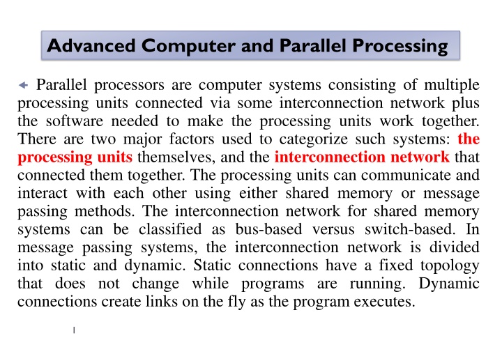
Advanced Computer and Parallel Processing Parallel processors are computer systems consisting of multiple processing units connected via some interconnection network plus the software needed to make the processing units work together. There are two major factors used to categorize such systems: the processing units themselves, and the interconnection network that connected them together. The processing units can communicate and interact with each other using either shared memory or message passing methods. The interconnection network for shared memory systems can be classified as bus-based versus switch-based. In message passing systems, the interconnection network is divided into static and dynamic. Static connections have a fixed topology that does not change while programs are running. Dynamic connections create links on the fly as the program executes. 1
Multiprocessor A multiprocessor is expected to reach faster speed than the fastest single-processor system. In addition, a multiprocessor consisting of a number of single processors is expected to be more cost-effective than building a high-performance single processor. Another advantage of a multiprocessor is fault tolerance. If a processor fails, the remaining processors should be able to provide continued service . Four Decades of Computing Most computer scientists agree that there have been four distinct paradigms of computing. 2
Current Trends One of the clear trends in computing is the substitution of expensive and specialized parallel machines by the more cost-effective clusters of workstations. A cluster is a collection of stand-alone computers connected using some interconnection network. Additionally, the pervasiveness of the Internet created interest in network computing and more recently in grid computing. Grids are geographically distributed platforms of computation. They should provide dependable, consistent, pervasive, and inexpensive access to high-end computational facilities. Flynn s Taxonomy of Computer Architecture The most popular taxonomy of computer architecture was defined by Flynn in 1966. Flynn s classification scheme is based on the notion of a stream of information. Two types of information flow into a processor: instructions and data. 1) (SISD) . 2) (SIMD). 3) (MISD). 4)(MIMD). 4
SISD architecture. SIMD architecture. 5
SIMD ARCHITECTURE The SIMD model of parallel computing consists of two parts: a front-end computer of the usual von Neumann style, and a processor array as shown in Figure. The processor array is a set of identical synchronized processing elements capable of simultaneously performing the same operation on different data. Each processor in the array has a small amount of local memory where the distributed data resides while it is being processed in parallel. The processor array is connected to the memory bus of the front end so that the front end can randomly access the local processor memories as if it were another memory. 6 SIMD architecture model.
A program can be developed and executed on the front end using a traditional serial programming language.. In SIMD architecture, parallelism is exploited by applying simultaneous operations across large sets of data. There are two main configurations that have been used in SIMD machines In the first scheme, each processor has its own local memory. Processors can communicate with each other through the interconnection network. If the interconnection network does not provide direct connection between a given pair of processors, then this pair can exchange data via an intermediate processor. In the second SIMD scheme, processors and memory modules communicate with each other via the interconnection network. Two processors can transfer data between each other via intermediate memory module(s) or possibly via intermediate processor(s). 7
MIMD Architecture Multiple-instruction multiple-data streams (MIMD) parallel architectures are made of multiple processors and multiple memory modules connected together via some interconnection network. They fall into two broad categories: shared memory or message passing. 9
Shared Memory Organization A shared memory model is one in which processors communicate by reading and writing locations in a shared memory that is equally accessible by all processors. Each processor may have registers, buffers, caches, and local memory banks as additional memory resources. These are typically server systems that communicate through a bus and cache memory controller. The bus/cache architecture alleviates the need for expensive multiport memories and interface circuitry . Because access to shared memory is balanced, these systems are also called SMP (symmetric multiprocessor) systems. Each processor has equal opportunity to read/write to memory, Access control determines which process accesses are possible to which resources. Access control table contains flags that determine the legality of each access attempt. Synchronization constraints limit the time of accesses from sharing processes to shared resources. Depending on the interconnection network, a shared memory system leads to systems can be classified as: uniform memory access (UMA), nonuniform memory access (NUMA), and cache-only memory architecture (COMA). 11
In the UMA system, a shared memory is accessible by all processors through an interconnection network in the same way a single processor accesses its memory , therefore all processors have equal access time to any memory location. The interconnection network used in the UMA can be a single bus, multiple buses, a crossbar, or a multiport memory. In the NUMA system, each processor has part of the shared memory attached. The memory has a single address space. Therefore, any processor could access any memory location directly using its real address. Similar to the NUMA, each processor has part of the shared memory in the COMA. However, in this case the shared memory consists of cache memory. A COMA system requires that data be migrated to the processor requesting it. 12
Message Passing Organization A message passing system (also referred to as distributed memory) typically combines the local memory and processor at each node of the interconnection network. A node in such a system consists of a processor and its local memory. Nodes are typically able to store messages in buffers (temporary memory locations where messages wait until they can be sent or received), and perform send/receive operations at the same time as processing. There is no global memory, so it is necessary to move data from one local memory to another by means of message passing. This is typically done by a Send/Receive pair of commands, which must be written into the application software by a programmer. which involves data copying and dealing with consistency issues. Commercial examples of message passing architectures C. 13
Two important design factors must be considered in designing interconnection networks for message passing systems. These are the link bandwidth and the network latency. The link bandwidth is defined as the number of bits that can be transmitted per unit time (bits/s). The network latency is defined as the time to complete a message transfer. Wormhole routing in message passing was introduced in 1987. In wormhole routing, a packet is divided into smaller units that are called flits (flow control bits) such that flits move in a pipeline fashion with the header flit of the packet leading the way to the destination node. When the header flit is blocked due to network congestion, the remaining flits are blocked as well. 14
Interconnection Networks Multiprocessors interconnection networks (INs) can be classified based on a number of criteria. These include (1) Mode of operation (synchronous versus asynchronous), (2) Control strategy (centralized versus decentralized), (3) Switching techniques (circuit versus packet), (4) Topology (static versus dynamic). 1- Mode of Operation According to the mode of operation, INs are classified as synchronous versus asynchronous. In synchronous mode of operation, a single global clock is used by all components in the system such that the whole system is operating in a lock step manner. Asynchronous mode of operation, on the other hand, does not require a global clock. Handshaking signals are used instead in order to coordinate the operation of asynchronous systems. While synchronous systems tend to be slower compared to asynchronous systems, they are race and hazard-free. 15
2- Control Strategy According to the control strategy, INs can be classified as centralized versus decentralized. In centralized control systems, a single central control unit is used to oversee and control the operation of the components of the system. In decentralized control, the control function is distributed among different components in the system. 3- Switching Techniques Interconnection networks can be classified according to the switching mechanism as circuit versus packet switching networks. In the circuit switching mechanism, a complete path has to be established prior to the start of communication between a source and a destination. . In a packet switching mechanism, communication between a source and destination takes place via messages that are divided into smaller entities, called packets. On their way to the destination, packets can be sent from a node to another in a store-and-forward manner until they reach their destination. While packet switching tends to use the network resources more efficiently compared to circuit switching, it suffers from variable packet delays. 16
4- Topology An interconnection network topology is a mapping function from the set of processors and memories onto the same set of processors and memories. In other words, the topology describes how to connect processors and memories to other processors and memories. A fully connected topology, for example, is a mapping in which each processor is connected to all other processors in the computer. A ring topology is a mapping that connects processor k to its neighbors, processors (k - 1) and (k + 1). In general, interconnection networks can be classified as static versus dynamic networks. In static networks, direct fixed links are established among nodes to form a fixed network, while in dynamic networks, connections are established as needed. Switching elements are used to establish connections among inputs and outputs. 17
Shared memory systems can be designed using bus-based or switch- based INs. The simplest IN for shared memory systems is the bus. However, the bus may get saturated if multiple processors are trying to access the shared memory (via the bus) simultaneously. A typical bus- based design uses caches to solve the bus contention problem. For example, a crossbar switch can be used to connect multiple processors to multiple memory modules. A crossbar switch, can be visualized as a mesh of wires with switches at the points of intersection. Message passing INs can be divided into static and dynamic. Static networks form all connections when the system is designed rather than when the connection is needed. In a static network, messages must be routed along established links. Dynamic INs establish a connection between two or more nodes on the fly as messages are routed along the links. The number of hops in a path from source to destination node is equal to the number of point-to-point links a message must traverse to reach its destination. 18
Shared memory interconnection networks. (a) bus-based and (b) switch-based shared memory systems bus-based systems when a single bus is used versus the case when multiple buses are used 19
Examples of static topologies. The single-stage interconnection network of Figure 1.10a is a simple dynamic network that connects each of the inputs on the left side to some, but not all, outputs on the right side through a single layer of binary switches represented by the rectangles. The binary switches can direct the message on the left-side input to one of two possible outputs on the right side. If we cascade enough single-stage networks together, they form a completely connected multistage interconnection network (MIN), 20
dynamic INs: (a) single-stage, (b) multistage, The omega MIN connects eight sources to eight destinations. The connection from the source 010 to the destination 010 is shown as a bold path. These are dynamic INs because the connection is made on the fly, as needed. In order to connect a source to a destination, we simply use a function of the bits of the source and destination addresses as instructions for dynamically selecting a path through the switches. For example, to connect source 111 to destination 001 in the omega network, the switches in the first and second stage must be set to connect to the upper output port, while the switch at the third stage must be set to connect to the lower output port (001). 21
The crossbar switch of Figure c provides a path from any input or source to any other output or destination by simply selecting a direction on the fly. To connect row 111 to column 001 requires only one binary switch at the intersection of the 111 input line and 011 output line to be set. The crossbar switch clearly uses more components; for example, N2 components are needed to connect NxN source/destination pairs. The omega MIN, on the other hand, connects NxN pairs with N/2(log N) components. The major advantage of the crossbar switch is its potential for speed. In one clock, a connection can be made between source and destination. The diameter of the crossbar is one. (Note: Diameter, D, of a network having N nodes is defined as the maximum shortest paths between any two nodes in the network). The omega MIN, on the other hand requires log N clocks to make a connection. The diameter of the omega MIN is therefore log N. binary switching (c) crossbar switch 22
Both networks limit the number of alternate paths between any source/destination pair. This leads to limited fault tolerance and network traffic congestion. If the single path between pairs becomes faulty, that pair cannot communicate. If two pairs attempt to communicate at the same time along a shared path, one pair must wait for the other. This is called blocking, and such MINs are called blocking networks. A network that can handle all possible connections without blocking is called a nonblocking network. TABLE shows a performance comparison among a number of different dynamic INs m = the number of multiple buses used, N = the number of processors (memory modules) or input/output of the network. 23
Table 3 shows a performance comparison among a number of static INs. In this table, the degree of a network is defined as the maximum number of links (channels) connected to any node in the network. The diameter of a network is defined as the maximum path, p, of the shortest paths between any two nodes. Degree of a node, d, is defined as the number of channels incident on the node. 24


 single-stage,")