Overview of Magnetic Sensors and Applications
Magnetic sensors play a crucial role in various applications such as navigation aids, orientation finding, and enhancing inertial measurement units. This technology utilizes magnetic field strength and flux density to detect and measure magnetic fields accurately. Different types of magnetic sensors are used, including Hall sensors and search coils, each serving specific purposes in industries like automotive and sensor systems. Explore the world of magnetic sensors and their diverse applications through this informative content.

Download Presentation

Please find below an Image/Link to download the presentation.
The content on the website is provided AS IS for your information and personal use only. It may not be sold, licensed, or shared on other websites without obtaining consent from the author.If you encounter any issues during the download, it is possible that the publisher has removed the file from their server.
You are allowed to download the files provided on this website for personal or commercial use, subject to the condition that they are used lawfully. All files are the property of their respective owners.
The content on the website is provided AS IS for your information and personal use only. It may not be sold, licensed, or shared on other websites without obtaining consent from the author.
E N D
Presentation Transcript
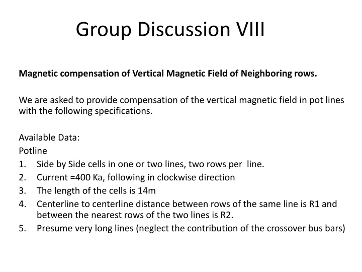
Group Discussion VIII Magnetic compensation of Vertical Magnetic Field of Neighboring rows. We are asked to provide compensation of the vertical magnetic field in pot lines with the following specifications. Available Data: Potline 1. Side by Side cells in one or two lines, two rows per line. 2. Current =400 Ka, following in clockwise direction 3. The length of the cells is 14m 4. Centerline to centerline distance between rows of the same line is R1 and between the nearest rows of the two lines is R2. 5. Presume very long lines (neglect the contribution of the crossover bus bars)
Group Discussion VIII Magnetic compensation of Vertical Magnetic Field of Neighboring rows. We are asked to provide compensation of the vertical magnetic field in pot lines with the following specifications. Available Data: Compensation Loop: 1. Distance from the cell centerline to the compensation loop =10m 2. Total length = 1000m 3. Current density in the compensation loop = 400 Ka /m2 4. Busbar density = 2700 kg/m3 5. Busbar resistivity = 0.035 6. Busbar cost = 3000 $ /ton 7. Cost of energy = 40 $ /MWH
Group Discussion VIII Question 1: First consider only one line in the smelter. What is the minimum distance between the two rows, which would give a maximum vertical field of 0.5 mT at the centre of the cells ? Discuss practical aspects of building such a line.
Group Discussion VIII Answer 1: Using the formula B= I / (5R) Where current is 400 kA, magnetic field of 0.5 mT, R = I / (5B) R=400 / 5*0.5 R = 160 m Conclusion is : Inorder to have the Bz field from the neighboring rows smaller than 0.5 mT, the pot rows should be at a distance >160 m. This is not practical since the plant will occupy lot of space. So to justify a compensation loop is better solution than separating potroom.
Group Discussion VIII Question 2: 1. In a two-line smelter, investigate the influence of different ratios of R2/R1 on the vertical magnetic field in each row. Specifically, take R1=80 m and determine R2 which would give complete self compensation of BZ in the two inner rows.
Group Discussion VIII Answer 2: R1= 80 m, R2 =? Magnetic field in the inner row indicated by yellow rectangle is; Bz=I/5 ( -1/R1 + 1/R2 1/(R1+R2)) This field should be ZERO for perfect compensation. 400/5 ( -1 /R1 + 1/R2 1/ (R1+R2)) =0 This equation can only be solved for the ratio of R2/R1 = X = 1/R1 (-1 + 1/X 1/(1+X)) =0 R2 = 0.618 The solution to this equation is X = R2/R1 = 0.618. For R1= 80 m, R2 = 49.4 m.
Group Discussion VIII Question 3: 1. In a one line smelter with a row-to-row distance of 80m, compensate BZ due to neighboring row with a single internal loop as shown in the lecture. Assuming that the loop is at the level of the liquid metal pad and that BZ at the cell centre is 0 . Calculate the current needed. With this current calculate BZ at the two ends of the cell. Is there a problem with this compensation ?
Group Discussion VIII Answer 3: Bz from neighboring row = - 400 kA / (5*80) = - 1.0 mT Current required in the (compensation loop) at a distance of 10 m from the centerline is 50 kA. Bz at near end of the Pot is calculated as = 400 / 5*73 = -1.1 mT Bz from the loop at near end = 50 / 5 *3 = 3.2 mT Total field at the near end = 3.2 mT BZ = 3.2 mT 1.1 mT = 2.1 mT Bz from the neighbor row of the pot line at far end = 400 kA/ (5*87) = -0.92 mT Bz from the loop at Far end = 50 / 5*17 = 0.59 mT Total field at far end = 0.59 mT 0.92 mT = - 0.33 mT Far side is under compensated Near Side is over compensated.
Group Discussion VIII Question 4: 1. In the smelter of problem 3) use a magnetic compensation loop around each building, carrying a current of 25 kA, calculate the magnetic field at the cell centre and at each end. Compare these fields with those found in problem 3). Is this compensation good ? The magnetic filed from the inner part of the loop and the outer part of the loop add up. Bloop at pot centre = 25 /(5*10) + 25 / (5*10) = 1.0 mT BZ from loop at near end = 25 / (5*3) = 1.6 mT Total at near end = 1.6 - 1.1 = 0.5 mT The compensation is good.
Group Discussion VIII Question 5: For a 25 kA compensation loop around each building, calculate the busbar cross section, bus bar voltage drop, busbar cost and the cost of energy dissipated in the compensation loop each year. A = I /j = 25kA / (400 kA / m2) = 0.0625 m2 Volume= 0.0625 x 1000m = 62.5 m3 Mass = 2700 x 62.5 = 168,750 kg = 168.75 tons Bus Bar Cost= 168.75 * 3000$ / ton = 506,000 $ for one compensation loop.
Group Discussion VIII Question 5: For a 25 kA compensation loop around each building, calculate the busbar cross section, bus bar voltage drop, busbar cost and the cost of energy dissipated in the compensation loop each year. Cost of Energy / Year: P = V * I V= R*I = 0.035 = 14 000 mV = 14 V So, P = 14 V * 25 kA P = 350 kW = 0.35 MW So energy cost is calculates as = 0.35 MW X 8760 (Total h / Year) = 3066 MWh = 3066 MWh* 40 $ (energy cost) = 122,640 $ / Year. m* 1000 m * 400 kA/m2