Online Discussion Boards: Best Practices Overview
Objectives, types, prompts, and grading strategies for online discussion boards as detailed by Julie Tedjeske Crane. Discover how to engage students effectively and enhance interactive learning experiences.

Download Presentation

Please find below an Image/Link to download the presentation.
The content on the website is provided AS IS for your information and personal use only. It may not be sold, licensed, or shared on other websites without obtaining consent from the author.If you encounter any issues during the download, it is possible that the publisher has removed the file from their server.
You are allowed to download the files provided on this website for personal or commercial use, subject to the condition that they are used lawfully. All files are the property of their respective owners.
The content on the website is provided AS IS for your information and personal use only. It may not be sold, licensed, or shared on other websites without obtaining consent from the author.
E N D
Presentation Transcript
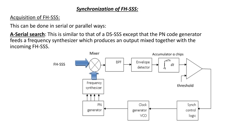
Synchronization of FH-SSS: Acquisition of FH-SSS: This can be done in serial or parallel ways: A-Serial search: This is similar to that of a DS-SSS except that the PN code generator feeds a frequency synthesizer which produces an output mixed together with the incoming FH-SSS. Mixer Accumulator chips FH-SSS threshold
The output of the envelope detector is high level whenever the local synthesized frequency is identical to that received, and if for example this test is repeated for frequencies ( chips), then the correlator output (integrator) will be greater than a specified threshold. The active high of the comparator will give a signal to a synch control logic to drive the clock generator (VCO) to lock with the incoming frequency hopping patterns. Searching has to be continued until the output of the correlator exceeds that threshold. b-Parallel search: The previous serial search may last long acquisition time until correct phase is reached. In stead, and at the expense of the hardware, a parallel search may be used using say m correlators as shown:
f1 V1 Synch indication f2 V2 FH-SSS Vm threshold fi f1 f2 f3 f4 f5. .fm fj fm
If the incoming hopping patterns matches with the preset pattern f1, f2, f3,.fm, then voltages v1, v2, v3, vmare all high and their sum exceeds a certain threshold to give a code start signal to the synch control logic. This will inform the VCO to lock on a correct state of the PN generator that controls the frequency synthesizer ( not shown in the figure and it is the same as in serial search). The delays are inserted so that when the correct hopping pattern appears, the voltages v1, v2, v3, vmwill occur at the same instant of time. Tracking system for FH-SSS Assuming that acquisition has been completed and that the time error between the Txand Rxhopping patterns is within one chip duration ( one hop duration). If there is still a time error of say second where < Thbetween the incoming frequencies and locally generated frequencies, this error is deleted using a tracking system.
Vd(t) Vg(t) Vp(t) FH-SSS V1(t) Vc(t) V2(t) local FH The timing waveforms explain the operation of such a tracking loop
V1(t) i/p FH-SSS f0 f1 f2 f4 f5 f3 V2(t) local FH- f0 f2 f3 f5 f1 f4 +1 Vd(t) 0 +1 Vc(t) -1 +1 0 Vg(t) -1 -ve VCO i/p
The BPF is made sufficiently wide to pass the product signal Vp(t). Note that V1(t) and V2(t) are at different frequencies fiand fi+1during the time. The output of the envelope detector Vd(t) is unity (high) when V1(t) and V2(t) are at the same frequency and is zero when V1(t) and V2(t) are at different frequencies. We see that Vg(t)=Vd(t) Vc(t) which is a 3- level signal being zero during the time interval . This 3-level signal Vg(t) is filtered using a LPF loop filter in a procedure quite similar to a phase locked loop (PLL) to generate a d.c. voltage Vc(t) that controls the frequency of the VCO. In the timing waveform shown, this d.c. voltage is ve to the VCO. If V2(t) is before V1(t), the d.c. voltage of the VCO is -ve, while if V2(t) is after V1(t) the d.c. voltage of the VCO is +ve. Correction is continued until both V1(t) and V2(t) are perfectly aligned.


")