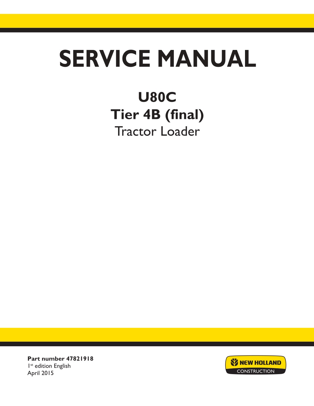
New Holland U80C Tier 4B (final) Tractor Loader Service Repair Manual Instant Download
Please open the website below to get the complete manualnn//
Download Presentation

Please find below an Image/Link to download the presentation.
The content on the website is provided AS IS for your information and personal use only. It may not be sold, licensed, or shared on other websites without obtaining consent from the author. Download presentation by click this link. If you encounter any issues during the download, it is possible that the publisher has removed the file from their server.
E N D
Presentation Transcript
SERVICE MANUAL U80C Tier 4B (final) Tractor Loader Part number 47821918 1st edition English April 2015 Printed in U.S.A. 2015 CNH Industrial America LLC. All Rights Reserved. New Holland is a trademark registered in the United States and many other countries, owned by or licensed to CNH Industrial N.V., its subsidiaries or affiliates.
SERVICE MANUAL U80C FOUR-WHEEL DRIVE (4WD) TIER 4B (FINAL) U80C TWO-WHEEL DRIVE (2WD) TIER 4B (FINAL) 47821918 22/04/2015 EN
Link Product / Engine Product Market Product North America Engine U80C FOUR-WHEEL DRIVE (4WD) TIER 4B (FINAL) U80C TWO-WHEEL DRIVE (2WD) TIER 4B (FINAL) F5HFL463D*F005 North America F5HFL463D*F005 47821918 22/04/2015
https://www.ebooklibonline.com Hello dear friend! Thank you very much for reading. Enter the link into your browser. The full manual is available for immediate download. https://www.ebooklibonline.com
Contents INTRODUCTION Engine....................................................................................... 10 [10.001] Engine and crankcase ............................................................. 10.1 [10.216] Fuel tanks .......................................................................... 10.2 [10.501] Exhaust Gas Recirculation (EGR) - Diesel Particulate Filter (DPF) exhaust treatment .................................................................................... 10.3 [10.400] Engine cooling system ............................................................. 10.4 [10.414] Fan and drive ...................................................................... 10.5 Transmission.............................................................................. 21 [21.112] Power shuttle transmission......................................................... 21.1 [21.134] Power shuttle transmission external controls ...................................... 21.2 [21.154] Power shuttle transmission internal components .................................. 21.3 Front axle system ....................................................................... 25 [25.100] Powered front axle ................................................................. 25.1 [25.102] Front bevel gear set and differential ............................................... 25.2 [25.108] Final drive hub, steering knuckles, and shafts ..................................... 25.3 [25.400] Non-powered front axle ............................................................ 25.4 Rear axle system........................................................................ 27 [27.100] Powered rear axle.................................................................. 27.1 [27.106] Rear bevel gear set and differential................................................ 27.2 [27.120] Planetary and final drives .......................................................... 27.3 Power Take-Off (PTO)................................................................. 31 [31.104] Rear electro-hydraulic control...................................................... 31.1 Hydraulic systems....................................................................... 35 [35.000] Hydraulic systems.................................................................. 35.1 [35.300] Reservoir, cooler, and filters........................................................ 35.2 47821918 22/04/2015
[35.104] Fixed displacement pump.......................................................... 35.3 [35.102] Pump control valves................................................................ 35.4 [35.350] Safety and main relief valves ...................................................... 35.5 [35.204] Remote control valves ............................................................. 35.6 [35.114] Three-point hitch control valve ..................................................... 35.7 [35.116] Three-point hitch cylinder .......................................................... 35.8 [35.723] Front loader bucket hydraulic system.............................................. 35.9 [35.734] Tool quick coupler hydraulic system ............................................. 35.10 Wheels...................................................................................... 44 [44.511] Front wheels........................................................................ 44.1 [44.520] Rear wheels........................................................................ 44.2 Cab climate control..................................................................... 50 [50.200] Air conditioning..................................................................... 50.1 Electrical systems....................................................................... 55 [55.100] Harnesses and connectors......................................................... 55.1 [55.525] Cab engine controls................................................................ 55.2 [55.991] Telematics.......................................................................... 55.3 [55.DTC] FAULT CODES.................................................................... 55.4 Front loader and bucket............................................................... 82 [82.100] Arm................................................................................. 82.1 [82.300] Bucket.............................................................................. 82.2 Platform, cab, bodywork, and decals............................................. 90 [90.150] Cab................................................................................. 90.1 [90.114] Operator protections ............................................................... 90.2 [90.105] Machine shields and guards ....................................................... 90.3 47821918 22/04/2015
INTRODUCTION 47821918 22/04/2015 1
INTRODUCTION Safety rules DANGER Improper operation or service of this machine can result in an accident. Do not operate this machine or perform any lubrication, maintenance, or repair on it until you have read and understood the operation, lubrication, maintenance, and repair information. Failure to comply will result in death or serious injury. D0010A WARNING Maintenance hazard! Always perform all service procedures punctually at the intervals stated in this manual. This ensures optimum performance levels and maximum safety during machine operation. Failure to comply could result in death or serious injury. W0132A WARNING Pressurized system! Before attempting any service procedure, it is your responsibility to know the number of accumulators on the machine, and the correct procedure for releasing the pressure of each accumulator. Failure to comply could result in death or serious injury. W0136A NOTICE: Extreme working and environmental conditions require shortened service intervals. Use Case fluids, lubricants, and filters for the best protection and performance of your machine. All fluids, lubricants, and filters must be disposed of in compliance with environmental standards and regulations. Contact your dealer with any questions regarding the service and maintenance of this machine. Read the safety decals and information decals on the machine. Read the Operator s Manual and safety manual. Understand the operation of the machine before you start any service. Before you service the machine, put a 'Do Not Operate' tag on the steering wheel or over the key switch. Ensure the tag is at a location where everyone who might operate or service the machine may see clearly. One tag is included with your new machine. Additional tags are available from your dealer. Plastic and resin parts Avoid using gasoline, paint thinner, etc. when cleaning plastic parts, console, instrument cluster, etc. Use only water, mild soap, and a soft cloth when you clean these parts. Using gasoline, thinners, etc. can cause discoloration, cracking, or deformation of the part being cleaned. 47821918 22/04/2015 3
INTRODUCTION Safety rules Ductile iron DANGER Improper operation or service of this machine can result in an accident. Any unauthorized modifications made to this machine can have serious consequences. Consult an authorized dealer on changes, additions, or modifications that may be required for this machine. Do not make any unauthorized modifications. Failure to comply will result in death or serious injury. D0030A Before you weld, cut, or drill holes on any part of this machine, make sure the part is not cast ductile iron. See your dealer if you do not know if a part is cast ductile iron. The following are cast ductile iron parts: two wheel drive steering link dump links front axle Air Conditioning (A/C) compressor mounting bracket Unauthorized modifications to cast ductile iron parts can cause injury or death. Welding, cutting, or drilling can cause cast ductile iron to break. Do not weld, cut, or drill to repair or to attach items to cast ductile iron parts on this machine. 47821918 22/04/2015 4
INTRODUCTION Safety rules Before welding on the machine you must do the following. If you have any questions about welding on the machine contact your dealer. Disconnect the batteries. Disconnect the alternator terminal wires. Disconnect the instrument cluster. Disconnect the engine control unit. Disconnect all con- nectors from the engine harness to the ECU. Disconnect the controller for the loader 4 in 1 bucket or auxiliaryhydraulics, ifequipped(oneconnector, located under the loader valve at the rear, left underside of the machine). 47821918 22/04/2015 5
INTRODUCTION Safety rules Unless otherwise instructed, always perform these steps before you service the machine: 1. Park the machine on a flat, level surface. 2. Place the loader bucket on the ground, with the bottom of the loader bucket parallel to the surface. 3. Place the direction control lever and the transmission in neutral. 4. If you need to open the hood to perform service, raise the loader arms and install the support strut. 5. Shut down the engine. 6. Place a 'Do Not Operate' tag on the key switch so that it is visible to other workers or remove the key. 47821918 22/04/2015 6
SERVICE MANUAL Engine U80C FOUR-WHEEL DRIVE (4WD) TIER 4B (FINAL) U80C TWO-WHEEL DRIVE (2WD) TIER 4B (FINAL) 47821918 22/04/2015 10
Engine - Engine and crankcase Engine - General specification Model Diesel, F5HFL463D*F005, Tier 4B (Final) emissions compliant Four cylinder, turbocharged 1-3-4-2 99 mm x 110 mm ( 3.90 in x 4.33 in) 3.4 L (207.5 in ) 17 to 1 Direct High Pressure Common Rail (HPCR) Type Firing order Bore and stroke Displacement Compression ratio Fuel injection Horsepower - rated at 2200 RPM Gross Net with 33 fan Net with viscous fan Peak torque at 1400 RPM Gross Net with 33 fan Net with viscous fan Maximum torque rise Engine speeds standard powertrain configuration Rated speed, full load Low idle High idle, no load Converter stall Loader stall Combined stall Engine speeds PTO or PTO ready powertrain configuration Rated speed, full load Low idle High idle, no load Converter stall Loader stall Combined stall 55 kW (75 Hp) 51 kW (69 Hp) 53.5 kW (72.7 Hp) 316 N m (233 lb ft) 298 N m (220 lb ft) 310 N m (229 lb ft) 35% 5 RPM 2200 RPM 900 - 1000 RPM 2330 - 2430 RPM 2025 - 2200 RPM 2150 - 2300 RPM 1450 - 1720 RPM 2200 RPM 900 - 1000 RPM 2330 - 2430 RPM 1925 - 2075 RPM 2150 - 2300 RPM 1375 - 1625 RPM 47821918 22/04/2015 10.1 [10.001] / 3
Engine - Engine and crankcase Engine - Exploded view 1. 2. 3. 4. 5. Bolt Washer Bracket, Left hand engine mount Mount Washer 6. 7. 8. 9. Nut Bolt Washer Bracket, Right hand engine mount 47821918 22/04/2015 10.1 [10.001] / 4
Engine - Engine and crankcase 1 RAIL12UTL0338GA 47821918 22/04/2015 10.1 [10.001] / 5
Engine - Engine and crankcase Engine - Drain fluid 1. Start the engine and run until the engine is warm. A warm engine allows a more complete removal of for- eign material. 2. Park on level ground, raise the loader arms, engage the safety support strut, and shut down the engine. 3. Clean the areas around the: Engine fill cap (1) Engine oil filter and head (2) (located underneath the fixed hood) Engine oil dipstick (3) Oil pan drain plug (not shown) 1 RAIL11TLB0008AA 4. Slowly open the drain plug for the engine oil pan and drain the oil into a suitable container. 2 RCPH11TLB016AAD 5. Install the drain plug for the engine oil tank. 47821918 22/04/2015 10.1 [10.001] / 6
Engine - Engine and crankcase Engine - Filling Engine oil specifications: 8.0 L (8.5 US qt) of NEW HOLLAND AMBRA UNITEK MASTERGOLD SBL CJ-4 SAE 10W-40. For machines operating in cold regions, see Engine oil viscosity - Recommended engine oil for operating temperature ranges Engine lubrication system - General specification (10.304). 1. Clean the areas around the: Engine fill cap (1) Engine oil filter and head (2) (located underneath the fixed hood) Engine oil dipstick (3) Oil pan drain plug (not shown) 1 RAIL11TLB0008AA 2. Make sure that the oil drain plug is installed. 2 RCPH11TLB016AAD 3. Put new oil into the engine. 4. If applicable, clear the Oil life reset active warning sym- bol for the display screen. See Oil life reset Engine oil system - Program (55.013). 47821918 22/04/2015 10.1 [10.001] / 7
Suggest: If the above button click is invalid. Please download this document first, and then click the above link to download the complete manual. Thank you so much for reading
Engine - Engine and crankcase Engine - Remove Prior operation: Remove the engine hood. See Engine hood - Remove (90.105). Prior operation: Remove the Particulate Matter Catalyst tray. See Diesel Oxidation Catalyst (DOC) - Remove (10.501) Prior operation: Drain the engine cooling system. See Radiator - Drain fluid (10.400). Prior operation: Remove the engine cooling system. See Radiator - Remove (10.400). Prior operation: If equipped, evacuate the air-conditioning system. See Air conditioning - Charging Air conditioner system evac- uation and recharging (50.200) 1. If equipped, disconnect the A/C high pressure line (1). 2. If equipped, disconnect electrical connectors (2) and (3). 3. If equipped, disconnect the A/C low pressure line (4). 4. If equipped, disconnect the A/C condenser voltage wire (5). 1 RAPH11TLB0045BA 5. Disconnect fuel lines (1) and (2). 2 RAPH11TLB0041BA 6. Disconnect the water sensor electrical connector (not shown). NOTE: Water sensor is located at the bottom of the primary fuel filter. 47821918 22/04/2015 10.1 [10.001] / 8
https://www.ebooklibonline.com Hello dear friend! Thank you very much for reading. Enter the link into your browser. The full manual is available for immediate download. https://www.ebooklibonline.com


