Networking Fundamentals and Challenges in Data Centers
Today's lecture covers definitions of routing and switching in networking, focusing on data center challenges, traffic patterns, fabric management, and parallelism within networks. The session also explores the role of switches and routers in data center and Internet design, emphasizing the importance of efficient data center networking to overcome challenges related to distances, speed of light, bandwidth management, and types of traffic.

Download Presentation

Please find below an Image/Link to download the presentation.
The content on the website is provided AS IS for your information and personal use only. It may not be sold, licensed, or shared on other websites without obtaining consent from the author.If you encounter any issues during the download, it is possible that the publisher has removed the file from their server.
You are allowed to download the files provided on this website for personal or commercial use, subject to the condition that they are used lawfully. All files are the property of their respective owners.
The content on the website is provided AS IS for your information and personal use only. It may not be sold, licensed, or shared on other websites without obtaining consent from the author.
E N D
Presentation Transcript
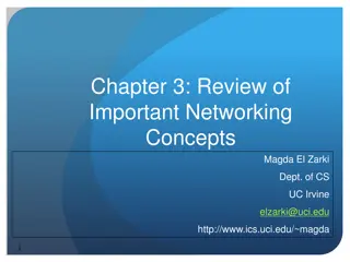
14-760: ADV. REAL-WORLD NETWORKS SWITCHING FABRIC, ROUTERS, ROUTING LECTURE 3 * SPRING 2019(KESDEN)
REMEMBER SOCRATIVE https://api.socrative.com/rc/FX5GFK
WHERE ARE WE? Last class Reviewed the basics of networking. Hopefully a refresher from prior class(es) Today Examine the role of switches and routers vis- -vis data center and Internet design Much of this will likely be a review for some (but not nearly all) Next class Look at the internals architecture of switches and routers. This is likely totally new to most.
TODAY Definitions Data Center Traffic Patterns Data Center Fabric Managing Parallelism Within Networks Routing and Routers/Internet Switches (This is probably mostly review) Looking forward to next class
DEFINITIONS FOR TODAY Routing (Network-layer packet switching) The hop-to-hop management of the movement of traffic among networks Switching (Link-layer frame switching) The movement of frames within a local network Note: There is nothing wrong with using the word switching at other-than the link layer, e.g. network layer switch, application layer switch, etc. Such references describe switches that make decisions based upon information present at other layers of the network stack That just doesn t happen to be the way I am using the words today, so I define them here for today s discussion.
TODAY Definitions Data Center Challenges and Traffic Patterns Data Center Fabric Managing Parallelism Within Networks Routing and Routers/Internet Switches (This is probably mostly review) Looking forward to next class
DC NETWORKING CHALLENGES Within a Data Center: Distances are short, the speed of light is less of a factor Serialization/Deserialization delay (bits/second) is a factor Managing bandwidth becomes complex as it is easy to add wire, but hard to use it. vs. Long haul: Speed of light is significant source of latency, unlikely to be resolved soon Additional bandwidth can typically readily be achieved with parallelism, e.g. more fiber
TYPES OF TRAFFIC Ingress Traffic entering from the outside, e.g. requests entering a data center Most commonly from outside requests. Can be from queries to related off-site services. Egress Traffic leaving to the outside, e.g. responses, streaming video, database results, etc. Most commonly from providing service. Can be queries to related off-site services East-West Traffic within a data center that crosses higher level switches Most commonly from communication within integrated services Incast Traffic within a data center that becomes concentrated Most commonly from parallel query concentrating results
TYPES OF TRAFFIC: INGRESS Core Aggregation Leaf
TYPES OF TRAFFIC: EGRESS Core Aggregation Leaf
TYPES OF TRAFFIC: EAST-WEST Core Aggregation Leaf
TYPES OF TRAFFIC: INCAST Core Aggregation Leaf
TODAY Definitions Data Center Challenges and Traffic Patterns Data Center Fabric Managing Parallelism Within Networks Routing and Routers/Internet Switches (This is probably mostly review) Looking forward to next class
NETWORK SWITCHES Ports connect to network segments Hosts and uplink at leaf level Other switches at other levels Switches have to move messages (frames, packets, etc) from one port to another Hardware solutions: Crossbar, etc Shared memory solutions: input and output queues Limited throughput (processor time, shared memory, crossbar, etc) Limited number of ports, limited throughput per port, limited aggregate throughput Commodity-level capacities are relatively affordable Trying to buy more capacity is expensive with limited gain
DC TOPOLOGY: VENERABLE 3-TIER Since, beyond a certain point, we can t make switches wider and/or faster, we need to fan out , most commonly with a tree topology Venerable 3-tier network is a straight-forward example: Core Aggregation Leaf
DC TOPOLOGY: VENERABLE 3-TIER WITH REDUNDANT CORE Can add a redundant core for increased throughput and resilience Core Aggregation Leaf
DC TOPOLOGY: VENERABLE 3-TIER, ANALYSIS Scales nicely, but Higher up gets over-subscribed since everything passes through Over-subscription increases with scale Request-to-stream and host-to-host cases generate bottlenecks 1-2 Switch Throughput W Switch Throughput W 2 Switch Throughput
DC TOPOLOGY: CLOS NETWORK Allocating an input port, and associated throughput, Allocates path whole way through. NxN connectivity with switches with less than NxN connectivity Basically a way to make a large NxN switch An expensive solution and not likely to need all throughput capacity simultaneously By Piggly (talk) (Uploads) - Transferred from en.wikipedia to Commons., Public Domain, https://commons.wikimedia.org/w/index.php?curid=61536102
DC TOPOLOGY: LEAF AND SPINE Type of Clos network Essentially folded, but still N-to-N connections Derived from old phone company architecture, invented in 1950s. Sometimes Called Folded Clos All paths are same length from edge to edge Need to pick path, as can choose any middle router Very redundant Can implement at layer-2 or layer-3
DC TOPOLOGY: FAT-TREES WITH SKINNY SWITCHES: GOALS Use all commodity switches Full throughput from host-to-host Compatible with usual TCP/IP stack Better energy efficiency per unit throughput from more smaller switches than fewer bigger switches As you look at the next slide note that, given K ports/switch, we are using: K/2 ports up + K/2 ports down, or K ports up, or K ports down
Note the replacement of aggregation layer switches with 2 layers of K/2 K-port switches (K/2)2 core routers FAT TREE (K=4) K PORTS/SWITCH K pods (K/2)2 servers per pod K-port switches support K3/4 servers Base Image Credit: Mysore, et al, "PortLand: a scalable fault-tolerant layer 2 data center network fabric", SIGCOM, October 2009, Pages 39-50.
DC TOPOLOGY: FAT TREE DETAILS K-ary fat free: three layers (core, aggregation, edge) Each pod consists of (K/2)2 servers and 2 layers of K/2 K-port switches. Each edge switch connects (K/2) servers to (K/2) aggregator switches Each aggregator switch connects (K/2) edge and (K/2) core switches (K/2)2 core switches, each ultimately connecting to K pods Providing K different roots, not 1. Trick is to pick different ones K-port switches support K3/4 servers/host: (K/2 hosts/switch * K/2 switches per pod * K pods)
DC TOPOLOGY: WHAT IS ACTUALLY USED? Redundant 3-Tier architectures Often used for general IT data centers They scale well Clos Networks Too expensive Not likely to be sufficiently utilized Fat Tree Networks Look good on paper and very practical Might use them, if we needed to Leaf-And-Spine Right now, port density seems to be supporting their use Not clear that next generation of switches won t trade bandwidth for port density and push us back to Fat Tree or other
DC TOPOLOGY: WHAT IS ACTUALLY USED? Note that there are many other possibilities, e.g. Grid/Cube-like architectures: Mesh, Torus, Hypercube, Butterfly, Dragonfly, HyperX, etc Note also that different parts of a data center, with different requirements may be networked differently, e.g. commodity file storage, vs bulk streaming, vs app servers, etc.
TODAY Definitions Data Center Traffic Patterns Data Center Fabric Managing Parallelism Within Networks Routing and Routers/Internet Switches (This is probably mostly review) Looking forward to next class
PARALLELISM WITHIN NETWORKS: TRADITIONAL THINKING Parallelism is for redundancy Run self-healing (periodically updating)a Spanning Tree Protocol (STP) among switches to agree a network tree without cycles Avoid frames being forwarded forever in loops Uses redundancy to select an alternate path in the event of hard failure
PARALLELISM WITHIN NETWORKS: BANDWIDTH-MOTIVATED THINKING Parallelism is for bandwidth Have parallelism where needed to support traffic patterns Find ways to use bandwidth without causing problems Avoid looping Use all available paths
PARALLELISM WITHIN NETWORKS: WHERE IS BANDWIDTH NEEDED? Depends upon usage pattern If most activity is rack-local At the rack switch 3-Tier might be fine If most of the activity is east-west Need more capacity at higher level(s), e.g. core and/or aggregation, etc If most of activity is concentrating at egress (or ingress) Need more core upstream capacity (supported by core)
PARALLELISM WITHIN NETWORKS: HOW TO USE PARALLELISM? Goals: Must avoid cycles Usage should be divided among paths Ways to divide usage Each use, e.g. network session, picks different path Uses divide their traffic among parallel paths
USING PARALLELISM WITHIN NETWORKS: SOLVABLE AT DIFFERENT LEVELS (EXAMPLES) MPTCP TCP that shares multiple paths for single session Creates many sub-sessions and multiplexes overarching session among them PORTland network Link-Layer solutions Path is based upon sender s location in network
TODAY Definitions Data Center Traffic Patterns Data Center Fabric Managing Parallelism Within Networks Routing and Routers/Internet Switches (This is probably mostly review) Looking forward to next class
ROUTING As we leave the domain of a single network, we enter the domain of internetworking Many techniques for global connectivity are possible, but packet switching is the most common for Internet traffic as it crosses providers Other types of switching, including (and perhaps especially) virtual circuits, e.g. ATM, are commonly used within provider networks. Circuit switching is a fading technology, e.g. POTS, ISDN. Packet switching involves a router making hop-by-hop decisions about how to route a packet.
ROUTERS May Also be called Internet Switches or Network-layer switches May also perform other roles Rule-based Firewalls Rule-based load-balancing Network Address Translation (NAT) Virtual Private Networks and Tunneling
ROUTING PROTOCOLS Routers exchange information with each other about the state of the network Routers collect this into routing tables Algorithms reduce the routing tables to simple forwarding tables that the switch can quickly consult w.r.t. which port should be the destination port for a particular incoming packet.
DATA PLANE VS CONTROL PLANE Routing algorithms run in the Control Plane The control plane decides the rules for forwarding, but it does not do the forwarding The Data Plan is where the forwarding actually occurs Packets move in and out via the data plane, which consults the distilled tables provided by the control plane
TODAY Definitions Data Center Traffic Patterns Data Center Fabric Managing Parallelism Within Networks Routing and Routers/Internet Switches (This is probably mostly review) Looking forward to next class
NEXT CLASS Routers and switches need to sustain a very, very high throughput. They need to very rapidly Source a packet Decide what to do with it Sink it to another port This could involve buffering it at the input port, for a decision, and/or at the output port This could involve a computer-like shared memory system or a more purpose-built hardware switch
NEXT CLASS, CONT. Next class, we are going to take a look a the architectures, where the points of contention are within them, discuss their performance and relative costs, &c.