Modelling Workflows and Data Domain in System Requirements and User Experience
In this lecture, the focus is on modelling workflows and data domain in the context of system requirements and user experience. The topics covered include recap of use cases, use case diagrams, descriptions, events initiated by stakeholders, defining elements for each use case, use case diagrams, and detailed use case descriptions with important fields like preconditions. The session emphasizes the graphical representation of use cases and actors, along with understanding the interactions between actors and the system.
Download Presentation

Please find below an Image/Link to download the presentation.
The content on the website is provided AS IS for your information and personal use only. It may not be sold, licensed, or shared on other websites without obtaining consent from the author.If you encounter any issues during the download, it is possible that the publisher has removed the file from their server.
You are allowed to download the files provided on this website for personal or commercial use, subject to the condition that they are used lawfully. All files are the property of their respective owners.
The content on the website is provided AS IS for your information and personal use only. It may not be sold, licensed, or shared on other websites without obtaining consent from the author.
E N D
Presentation Transcript
INFS 1026 System Requirements and User Experience Lecture 7: Modelling Workflows and Data Domain
2 Recap Use Cases, Use Case Diagrams, Use Case Descriptions
3 Recap Use cases Events initiated by first or second degree stakeholders Breakdown of functional requirements and reflect user story goals Compare to functions in your code or low level menu options Related to recording of business transactions and display of information
4 Recap Elements to define for each use case Name Present tense verb + object Verb like if you are giving a command Browse options List of actors May be multiple people who initiate the use case Brief use case description Summary of the interaction between the actor and the system Formatted as The actor and the system
5 Recap Use case diagram Graphical representation of use cases and the actors who initiate them Mandatory components to include for each diagram Title Automation boundary Actors Labelled use cases Associations between actors and use cases Dashed arrows to represent <<includes>> and <<extends>> Required to use draw.io / diagrams.net and required graphic
6 Recap Use Case Description More complete description of a use case Use case may have scenarios / variations in what activities are performed if multiple actors or differences depending on circumstances Template elements on the right Important to understand what is to be included for each component Always related to the system
7 Recap Use case description - Important fields Preconditions What conditions within the system must be present before the use case may begin If adding a record, you may need to check if the record does not already exist in the database Information / database records existence required before the use case can begin eg scheduling for the next semester complete before enrolments can be done Not related to if the actor has all required information Check that systems / subsystems / external systems are active / available
8 Recap Use case description - Important fields Success Guarantee / Postconditions What must be true for the use case to be successfully complete New objects and associations created in the database Information created / made available Eg enrolment successful if enrolment objects created and associated with student and classes Timetable made available
9 Recap Use case description - Important fields Main success scenario Numbered steps taken by the actor and associated steps by the system Can have multiple steps undertaken by the system for each step by the actor Actor steps 1, 2, 3 etc System steps 1.1, 1.2, 2.1, 3.1, 3.2, 3.3
10 Recap Use case description - Important fields Extensions Alternative paths due to Validation if x then y else z Identify the number of the system activity leading to the extension Validation check for valid data entry Process error Provide options for the user to exit the use case early or an alternate
11 Modelling Workflows Activity Diagrams
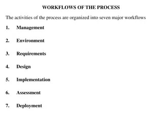
12 Activity Diagrams Use to Show the flow of control between activities to complete a task Help to Model work flow within business processes Understand what actions need to be complete for a use case Model the sequential and concurrent steps in a computational process Help identifying extensions in a use case
13 Activity Diagrams Modelling workflows May have multiple actors and multiple subsystems Shows flow of work / communication between different departments and subsystems May represent multiple use cases
14 Workflow VS Use Case Modelling use case descriptions Show communication between the actor and the system Represent the main success scenario One actor, one system Each actor activity immediately followed by one or more system activities
15 Creating Activity Diagrams Identify Actors, systems or subsystems Loops For all Decisions If <condition> then <action 1> else <action 2> Synchronous activities While <activity 1> <activity 2> Activities
16 Activity Diagram Use Case Demonstration Main Success Scenario: 1. Student selects course 1a System displays available classes 2. Student selects class from displayed classes for the course 2a System creates enrolment 2b System associates with the student and class 3. Student repeats until enrolled in all required courses 3a System displays timetable 4. Student views the timetable and verifies enrolments complete 4a System calculates fees due 4b System displays fees due 5. Student selects to make payment 5a System calls Make payment use case
17 Activity Diagram Use Case Demonstration Extensions: 1a: Student has not completed pre-requisites for the selected course 1a1: Student quits enrolments 1a2: Student selects alternative course 2a: Class full 2a1: Student quits enrolments 2a2: Student selects alternative class 2b: No more courses required not maximum number / for loop exit point 2b1: Students confirms enrolment complete 5a: Student delays make payment 5a1: Student quits enrolment
18 Activity Diagram Use Case Demonstration Actors, systems or subsystems Student, System Loops For each course / until no more classes to enrol in / maximum 4 courses Decisions As per extensions Synchronous activities None
19 Activity Diagram Use Case Demonstration Activity labels have the same format as use case names Use Case Descriptor Student selects course System displays available classes Student selects class from displayed classes for the course System creates enrolment System associates with the student and class Actor Student System Student Activity Label Select course Display available classes Select class System System Create enrolment Associate enrolment with student and class
20 Activity Diagram Use Case Demonstration Activity labels have the same format as use case names Use Case Descriptor System displays timetable Student views the timetable and verifies enrolments complete System calculates fees due System displays fees due Student selects to make payment System calls Make payment use case System Actor System Student Activity Label Display timetable Verify enrolment complete Calculate fees due Display fees due Select make payment Call Make Payment System System Student
21 Activity Diagram Use Case Demonstration Extensions: 1a: Student has not completed pre-requisites for the selected course 1a1: Student quits enrolments 1a2: Student selects alternative course 2a: Class full 2a1: Student quits enrolments 2a2: Student selects alternative class 2b: No more classes required 2b1: Students confirms enrolment complete 5a: Student delays make payment 5a1: Student quits enrolment
22 Activity Diagram Use Case Demonstration Activity labels have the same format as use case names Use Case Descriptor Student quits enrolments Student selects alternative course Actor Activity Label <arrow to end> <arrow to previous activity select course <arrow to previous activity select class > Confirm enrolment complete Student selects alternative class Students confirms enrolment complete Student
23 Activity Diagram Use Case Demonstration Symbols Advanced vertical pool / swimlanes Need to select one and delete or copy depending on how many needed
24 Activity Diagram Use Case Demonstration Symbols UML Referred to as a Synchronisation Bar
25 Activity Diagram Example Delete or add swimlanes as necessary Label the diagram Label swimlanes with actors Select UML shapes dropdown Scroll to activity diagram symbols Select Start event Drag to top of left swimlane
26 Activity Diagram Example Add the for loop Insert synchronisation bar Label bar Add activities for the for loop Select course -> Display timetable End for loop Insert synchronisation bar Label bar
27 Activity Diagram Example Add activities Verify enrolment Prompt to make payment Add decision make payment? Yes System calls use case No No additional activity Add end event
28 Synchronous Activities Consider the sequence While the customer waits in line they play a game on their phone While the customer loads the conveyor, the cashier scans the items Activities occur at the same time / synchronous Wait in line / Play game Load conveyor / Scan items
29 Activity Diagram Rules All symbols except the start event must have at least one entry and exactly one exit Multiple entry points to a symbol ok Only synchronisation bars may have multiple exits to show synchronous activities Start event must be in the far left swimlane Synchronous activities would not occur for use case activity diagrams Activities are only ever sequential
30 Domain Modelling
31 Data Modelling Understand the difference between modelling the data In Data Driven Web Technologies or Database Fundamentals Analysis = conceptual design Design = UML translation Implementation -> SQL For SRUX, concentrate on analysis only Domain model class diagram
32 Domain Modelling Domain model Class Diagram Analytical perspective of the database Represent items users work with when accomplishing tasks that need to be remembered Represented as domain classes, attributes and associations
33 Domain Modelling Domain model Class Diagram Each domain class denotes a type of object Describes of a set of things which share common features Eg Students, courses, semesters, grades, programs, classes Attributes denote the class characteristics Students have an id, name, email, username etc Associations denote how data in one class is related to another Students enrol in courses Courses are delivered in classes attended by students
34 Identifying Domain Classes from Use Cases Use cases identify objects which are manipulated Identify classes and associations from use case description Use case name helps identify some classes involved in the task Create submission, view sales report
35 Identifying Domain Classes from Use Cases Identify classes and associations from use case description Additional classes and associations Identified in pre and post conditions Preconditions - enrolment, student and course subsystems must be available Post conditions create enrolment; associateenrolment with student and course; create class enrolment; associate class enrolment with enrolment and student
36 Identifying Domain Classes from Scenarios Identify classes and associations from scenarios To offer books for sale, a person must register with TheEyesHaveIt.com. The person must provide a current physical address and telephone number as well as a current e-mail address. The system then maintains an open account for this person. Access to the system as a seller is through a secure, authenticated portal. Identify books, sale, person and account Books relate to sale; person is a seller who posts details about books for sale
37 Domain Attributes Each class has attributes Describe the characteristics of the class objects Each class must have One primary key Unique identifier of each class object / database record Used to create relationships to other objects Student Id links the student to their enrolments, attendance, grades At least one additional attribute A student has a name, address, date of birth etc
38 Domain Attributes Identifying attributes from scenarios To offer books for sale, a person must register with TheEyesHaveIt.com. The person must provide a current physical address and telephone number as well as a current e- mail address. The system then maintains an open account for this person. Access to the system as a seller is through a secure, authenticated portal. Identifying attributes from use cases Main success scenario often identifies what data is to be entered Data = attribute value
39 Domain Attributes Class and attribute representation In draw.io select Class 2 Analysis describes what is needed Class name Camel case, initial capital, capital for subsequent words Attribute names Camel case, initial lower case, capital for subsequent words No spaces, avoid digits with names Primary key identified with {key} Do not include field size, type or methods
40 Identifying Associations Identified in post conditions associate X with Y Post conditions create enrolment; associateenrolment with student and course; create class enrolment; associateclass enrolment with enrolment and student Two statements associated with each association between a pair of classes One course has many students One student enrols in many courses
41 Identifying Associations Need to give the association a name to describe it A student enrols in a course A student s assignment is graded by a lecturer Determine multiplicity of each association Number of links between the object instances of the classes Two multiplicities for each link between classes Each multiplicity will have a maximum and a minimum Minimum 0 or 1 or a specific number Maximum 1 or many or a specific number
42 Identifying Associations Minimum multiplicity Identified through business rules A customer must exist before they can purchase / create a sale If the an object is added to one class, does there have to be an associated object in the other class? If a new student is added to the database, do they have to be enrolled in a course immediately? -> minimum multiplicity student to course is zero If a customer purchases an item online, the customer must exist before they can continue to the purchase -> minimum multiplicity customer to sale is 1, sale to customer is 1
43 Identifying Associations Complete association description One student enrols in zero or many courses One course has enrolments for zero or many students Representing association in the domain model class diagram 0..* represents a minimum multiplicity of 0 and maximum of many 1..1 represents a minimum multiplicity of 1 and a maximum of 1
44 Association Description
45 Class symbols draw.io Add the association using Association 1 Select parent and child to add multiplicities Add text for the association name / description General - Triangle 10 x 10 for direction of the association
46 Examples Competition results, including the compiled best on court nominations from each week, and team results must be entered as soon as possible after the game ends. The teams coaches must enter the scores and details of players who participated in the match. Umpires need to add information about injuries or players being warned or sent off during the game. The club has identified that entering these details should be entered on a mobile phone for greatest convenience. Attributes Classes
47 Examples From the information need Competition with results each week Best on court nominations as attributes Team results Player details Umpires Injuries Problems
48 Example Class Umpire Attributes name, phone, email, mobile, level, dateEarned name, manager, coach, level player, preferredPosition name, address, phone, email, mobile, dateOfBirth, gender Description Details about the umpires including which level they can umpire and when they earned the qualification / badge Team details with links to the people involved Links to the players in the team and their preferred position Details about each player Team TeamPlayer Player
49 Example Class Competition date, time, court, team1, team2, result, umpire1, umpire2 Attributes Description Each instance of the competition. Created with date, time, venue and teams as soon as teams are sorted from grading. Links to the teams who play and umpires Record any injuries suffered during a game, whether an ambulance was called and any treatment Injuries game, player, time reportingUmpire, injuryDescription, ambulanceRequired, firstAider
50 Example Class TeamResults player, startPosition, timeOnCourt, goalsScored, goalsMissed GameIssues game, team, playerInvolved, time reportingUmpire, problemDescription, resolution Attributes Description For each game, which players were on court, what was their starting position, how long were they on court for, how many goals did they score or miss Record any problems reported during the game player warned or sent off, description of the issue and resolution
