Mobile Computing and TCP/IP Protocol Suite

MOBILE IP
1
Introduction
Mobile Computing
is becoming increasingly important due to the
rise in the number of portable computers
and the
desire to have
continuous network connectivity to the Internet irrespective of the
physical location of the node.
The Internet infrastructure is built on top of a collection of
protocols, called the TCP/IP protocol suite.
* Transmission Control Protocol (TCP)
*Internet Protocol (IP) are the core protocols in this suite.
2
IP requires the location of any host connected to the Internet to be uniquely
identified by an assigned IP address.
This raises one of the most important issues in mobility, because when a host moves to
another physical location, it has to change its IP address.
However, the higher level protocols require IP address of a host to be fixed for
identifying connections.
The Mobile Internet Protocol (Mobile IP) is an extension to the Internet Protocol
proposed by the Internet Engineering Task Force (IETF) that addresses this issue.
It enables mobile computers to stay connected to the Internet regardless of their
location and without changing their IP address. More precisely, Mobile IP is a
standard protocol that builds on the Internet Protocol by making mobility
transparent to applications and higher level protocols like TCP.
3
The TCP/IP Protocol Suite
TCP/IP protocol suite is a four-layer system. Each layer is
responsible for a specific task .
The four layers, from top to bottom, are
1- application layer,
2- transport layer,
3- network layer,
4- link layer.
The
application layer
handles the details of the particular application
(e.g., FTP, TELNET, HTTP etc.).
4
The transport layer :
provides a flow of data between two
Internet nodes.
There are two widely used transport layer protocols on the
Internet:
1.
TCP
(Transmission Control Protocol) :
provides a reliable flow
of data between two nodes by maintaining a connection-
oriented environment.
2.
UDP
(User Datagram Protocol) : provides an unreliable and
connectionless datagram service.
5
The network layer
handles the movement of packets
around the network by implementing efficient routing
algorithms. IP (Internet Protocol) , the default network
layer protocol on the Internet, is described in detail in the
next section.
The link layer
provides interfaces to the network
hardware devices in the form of device drivers.
6
Brief Overview of IPv4
network layer
, the Internet is viewed as a set of networks or
autonomous systems connected together in a hierarchical manner.
IP is the mechanism that connects these networks together. Its basic
function is to deliver data from a source to a destination independent of
the physical location of the two.
IP identifies each node uniquely, using an
IP address
that designates
its physical attachment to the Internet.
IP addresses are 32-bit long integers and are represented in a dotted
decimal format (e.g., 128.55.44.1), for ease of use.
7
Brief Overview of IPv4
Every
IP packet consists
of an IP header and an IP payload.
The
header contains
the IP addresses of the sending node and the
receiving node along with some other information.
To correctly deliver these packets, IP executes two major steps:
1)
Packet routing
involves use of protocols like BGP, RIP, and
OSPF to decide the route that each packet has to travel. The
route is decided using a routing table of < destination address,
next hop > pairs at each router. Destination addresses are
paired with a pair contained in the routing table.
2)
Packet forwarding
involves use of protocols like ARP etc. to
deliver the packet to the end node once it has arrived at the
destination network. This is typically done by discovering the
hardware address of the host corresponding to its IP address.
8
Motivation for the Mobile IP design
The IP address of a host consists of two parts :
1) The higher order bits of the address
determine the network on which the host
resides;
2) The remaining low-order bits determine the
host number.
9
IP decides the next-hop
by determining the network information from
the
destination IP address
of the packet. Thus, while trying to support
mobility on the Internet under the existing protocol suite, we are faced
with two mutually conflicting requirements:
1)
a mobile node has to change its IP address whenever it changes
its point of attachment, so that packets destined to the node are
routed correctly,
2)
to maintain existing TCP connections, the mobile node has to
keep its IP address the same. Changing the IP address will cause
the connection to be disrupted and lost.
10
Mobile IP, the standard proposed by IETF, is designed to solve the problem
by allowing each mobile node to have two IP addresses and by
transparently maintaining the binding between the two addresses [9].
Permanent home address
that is assigned at the home network and is used
to identify communication endpoints.
1.
Temporary care-of address
that represents the current location of the
host.
The main goals of Mobile IP are to make mobility
transparent to the higher
level protocols
and to
make minimum changes to the existing Internet
infrastructure
.
11
Mobile IP Entities
Mobile IP is consisting of the following entities:
Mobile Node (MN):
A host or router that may change its point of attachment from one network or
sub network to another through the internet. This entity is pre-assigned a fixed home address on a
home network, which other correspondent hosts will use to address their packets to, regardless of
its current location.
Home Agent (HA):
A router that maintains a list of registered mobile nodes in a visitor list. It is
used to forward mobile node-addressed packets to the appropriate local network when the mobile
nodes are away from home. After checking with the current mobility bindings for a particular
mobile node, it encapsulates (see below) datagrams and sends it to the mobile host's current
temporary address when the mobile node.
Foreign Agent (FA):
A router that assists a locally reachable mobile node that is away from its
home network. It delivers information between the mobile node and the home agent.
12
Care-of-address (COA):
An address which identifies the mobile node's current location. It can be
viewed as the end of a tunnel (see below) directed towards a mobile node. It can be either assigned
dynamically or associated with its foreign agent.
Correspondent Node (CN):
This node sends the packets which are addressed to the
mobile node.
Home Address:
A permanent IP address that is assigned to a mobile node. It remains
unchanged regardless of where the mobile node is attached to the internet.
Mobility Agent:
An agent which supports mobility. It could be either a home
agent or a foreign agent.
Tunnel:
The path which is taken by encapsulated packets. It is the path which leads
packets from the home agent to the foreign agent.
13
Overview of the Protocol:
Mobile IP supports mobility by transparently binding the
home address of the mobile node
with its
care-of address
.
This mobility binding is maintained by some specialized
routers known as mobility agents.
Mobility agents are of two types - home agents and foreign
agents.
14
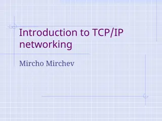
a designated router in the home network of the mobile node, maintains the mobility binding
in
a mobility binding table
where each entry is identified by
the
tuple <permanent home address, temporary care-of
address, association lifetime
>.
The purpose of this table
is to map a mobile node's home address with its care-of address and
forward packets accordingly.
Figure 1: Mobility Binding Table
The home agent
,
15
are specialized routers on the foreign network where the
mobile node is currently visiting.
The foreign agent maintains
a visitor list
which contains
information about the mobile nodes currently visiting that
network. Each entry in the visitor list is identified by
the tuple:
< permanent home address, home agent address,
media address of the mobile node, association lifetime>.
Foreign agents
16
In a typical scenario,
the
care-of address of a mobile node
is the foreign agent's IP address.
There can be another kind of care-of address, known as
Co
-
located care-of address
, which is usually obtained by
some external address assignment mechanism.
17
The basic Mobile IP protocol has four distinct
stages. These are:
1.
Agent Discovery: Agent Discovery consists of the
following steps:
1)
Mobility agents advertise their presence by periodically broadcasting Agent
Advertisement messages. An Agent Advertisement message lists one or more care-of
addresses and a flag indicating whether it is a home agent or a foreign agent.
2)
The mobile node receiving the Agent Advertisement message observes whether the
message is from its own home agent and determines whether it is on the home
network or a foreign network.
3)
If a mobile node does not wish to wait for the periodic advertisement, it can send
out Agent Solicitation messages that will be responded by a mobility agent.
18
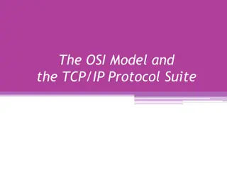
2. Registration: Registration consists of the
following steps:
1)
If a mobile node discovers that it is on the home network, it operates without any
mobility services.
2)
If the mobile node is on a new network, it registers with the foreign agent by sending
a Registration Request message which includes the permanent IP address of the
mobile host and the IP address of its home agent.
3)
The foreign agent in turn performs the registration process on behalf of the mobile
host by sending a Registration Request containing the permanent IP address of the
mobile node and the IP address of the foreign agent to the home agent.
4)
When the home agent receives the Registration Request, it updates the mobility
binding by associating the care-of address of the mobile node with its home address.
5)
The home agent then sends an acknowledgement to the foreign agent.
6)
The foreign agent in turn updates its visitor list by inserting the entry for the mobile
node and relays the reply to the mobile node.
19
Figure 3 illustrates the registration process.
20
3.
In Service: This stage can be subdivided into
the following steps:
1.
When a correspondent node wants to communicate with the mobile node, it
sends an IP packet addressed to the permanent IP address of the mobile node.
2.
The home agent intercepts this packet and consult the mobility binding table
to find out if the mobile node is currently visiting any other network.
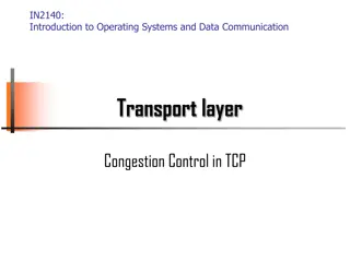
3.
The home agent finds out the mobile node's care-of address and constructs a
new IP header that contains the mobile node's care-of address as the
destination IP address. The original IP packet is put into the payload of this
IP packet. It then sends the packet. This process of encapsulating one IP
packet into the payload of another is known
as IP-within-IP
encapsulation
,
or tunneling
.
21
4.
When the encapsulated packet reaches the mobile node's current network,
the foreign agent decapsulates the packet and finds out the mobile node's
home address. It then consults the visitor list to see if it has an entry for
that mobile node.
5.
If there is an entry for the mobile node on the visitor list, the foreign agent
retrieves the corresponding media address and relays it to the mobile
node.
6.
When the mobile node wants to send a message to a correspondent node,
it forwards the packet to the foreign agent, which in turn relays the packet
to the correspondent node using normal IP routing.
7.
The foreign agent continues serving the mobile node until the granted
lifetime expires. If the mobile node wants to continue the service, it has
to reissue the Registration Request.
22
Figure 4: Tunneling operation in Mobile IP
23
Deregistration:
If a mobile node wants to drop its care-of address, it has to deregister with
its home agent. It achieves this by sending a Registration Request with the
lifetime set to zero.
There is no need for deregistering with the foreign agent as registration
automatically expires when lifetime becomes zero. However if the mobile
node visits a new network, the old foreign network does not know the new
care-of address of the mobile node. Thus datagrams already forwarded by
the home agent to the old foreign agent of the mobile node are lost.
24
INTRODUCTION
I
Global System Mobility
(GSM)
s the most successful digital mobile
telecommunication system in the world
today. It is used by over 800 million people
in more than 190 countries. GSM permits
the integration of different voice and
data services and the interworking with
existing networks. Services make a
network interesting for customers
Listed below are the features of GSM that account for its popularity and wide
acceptance.
International roaming
Low-cost mobile sets and base stations (BSs)
High-quality speech
Compatibility with Integrated Services Digital Network (ISDN) and other
telephone company services
Support for new services
INTRODUCTION
GSM Network Areas
In a GSM network, the following areas are defined:
Cell: Cell is the basic service area; one BTS covers one cell. Each cell is
given a Cell Global Identity (CGI), a number that uniquely identifies the
cell.
Location Area: A group of cells form a Location Area (LA). This is the area
that is paged when a subscriber gets an incoming call. Each LA is assigned
a Location Area Identity (LAI). Each LA is served by one or more BSCs.
MSC/VLR Service Area: The area covered by one MSC is called the MSC/VLR
service area.
PLMN: The area covered by one network operator is called the Public Land
Mobile Network (PLMN). A PLMN can contain one or more MSCs.
GSM Network Areas
GSM ARCITECTURE
The GSM technical specifications define the different elements within the
GSM network architecture. It defines the different elements and the ways in
which they interact to enable the overall system operation to be maintained.
The GSM network architecture is now well established and with the other
later cellular systems now established and other new ones being deployed, the
basic GSM network architecture has been updated to interface to the network
elements required by these systems.
Despite the developments of the newer systems, the basic GSM system
architecture has been maintained, and the network elements described below
perform the same functions as they did when the original GSM system was
launched in the early 1990s.GSM network architecture elements
The GSM network architecture as defined in the GSM
specifications can be grouped into four main areas:
1.
Mobile station (MS)
2.
Base-Station Subsystem (BSS)
3.
Network and Switching Subsystem (NSS)
4.
Operation and Support Subsystem (OSS)
The different elements of the GSM network operate together and
the user is not aware of the different entities within the system.
GSM ARCITECTURE
The GSM system architecture contains a variety of
different elements, and is often termed the core network.
It provides the main control and interfacing for the whole
mobile network. The major elements within the core
network include:
1.
MSC
(
Mobile Services Switching Centre
)
2.
HLR
(
Home Location Register
)
3.
VLR
(
Visitor Location Register)
4.
EIR
(
Equipment Identity Register
)
5.
AuC
(
Authentication Centre)
6.
SMS-G
(SMS Gateway)
7.
GMSC
(Gateway Mobile Switching Centre)
A basic diagram of the overall GSM system architecture with these
four major elements is shown below:
Simplified diagram of the architecture of a typical GSM network showing the
main elements in the base station subsystem, network and switching subsystem as
well as the operation and support subsystem.
1.
MS (MOBILE STATION)
it consist
s
of
1.
Mobile stations (MS)
2.
mobile equipment (ME
)
or as they are most widely known, cell
or mobile phones are the section of a GSM cellular network that
the user sees and operates. In recent years their size has fallen
dramatically while the level of functionality has greatly increased.
A further advantage is that the time between charges has
significantly increased.
There are a number of elements to the cell phone, although
the two main elements are the
main
hardware
and
the SIM
.
The hardware
itself contains the main elements of the
mobile phone including the display, case, battery,
and the electronics used to generate the signal,
and process the data receiver and to be transmitted.
It also contains a number known as
the International
Mobile Equipment Identity
(IMEI).
This is installed in the
phone at manufacture and "cannot" be changed. It is accessed
by the network during registration to check whether the
equipment has been reported as stolen.
The SIM
or
Subscriber Identity Module
contains the information that provides the identity of the
user to the network.
It contains are variety of information including a number
known as
the International Mobile Subscriber
Identity (IMSI).
2
.
BSS (BASE STATION SUBSYSTEM)
The Base Station Subsystem (BSS) section of the GSM network architecture that is
fundamentally associated with communicating with the mobiles on the network. It consists of
two elements:
1.
Base Transceiver Station (BTS):
The BTS used in a GSM network comprises the radio transmitter receivers,
and their associated antennas that transmit and receive to directly
communicate with the mobiles.
The BTS is the defining element for each cell.
The BTS communicates with the mobiles and the interface between the two is
known as
the Um interface
with its associated protocols.
2.
Base Station Controller (BSC):
The BSC forms the next stage back into the GSM network.
It controls a group of BTSs, and is often co-located with
one of the BTSs in its group.
It manages the radio resources and controls items such as
handover within the group of BTSs, allocates channels
and the like.
It communicates with the BTSs over what is termed the
Abis interface.
3. NSS (NETWORK STATION SUBSYSTEM)
The GSM system architecture contains a variety of
different elements, and is often termed the core network.
It provides the main control and interfacing for the whole
mobile network. The major elements within the core
network include:
1.
MSC
(
Mobile Services Switching Centre
)
2.
HLR
(
Home Location Register
)
3.
VLR
(
Visitor Location Register)
4.
EIR
(
Equipment Identity Register
)
5.
AuC
(
Authentication Centre)
6.
SMS-G
(SMS Gateway)
7.
GMSC
(Gateway Mobile Switching Centre)
1.
Mobile Services Switching Centre (MSC):
The main element within the core network area of the overall GSM network
architecture is the
Mobile switching Services Centre
(MSC).
The MSC acts like a normal switching node within a PSTN or ISDN,
but also provides additional functionality to enable the requirements
of a mobile user to be supported. These include
registration,
authentication,
call location,
inter-MSC handovers and call routing to a mobile subscriber.
It also provides an interface to the PSTN so that calls can be routed
from the mobile network to a phone connected to a landline.
Interfaces to other MSCs are provided to enable calls to be made to
mobiles on different networks.
2. Home Location Register (HLR):
This database contains all the administrative information
about each subscriber
along with their last known location.
In this way, the GSM network is able to route calls to the relevant
base station for the MS.
When a user switches on their phone, the phone registers with the
network and from this it is possible to determine which BTS it
communicates with so that incoming calls can be routed
appropriately.
Even when the phone is not active (but switched on) it re-
registers periodically to ensure that the network (HLR) is
aware of its latest position.
There is one HLR per network, although it may be distributed
across various sub-centres to for operational reasons.
3.
Visitor Location Register (VLR):
This contains selected information from the HLR that
enables the selected services for the individual
subscriber to be provided.
The VLR can be implemented as a separate entity, but it
is commonly realised as an integral part of the MSC,
rather than a separate entity. In this way access is made
faster and more convenient.
4.
Equipment Identity Register (EIR):
The EIR is the entity that decides whether a given mobile
equipment may be allowed onto the network.
Each mobile equipment has a number known as the International
Mobile Equipment Identity
(IMEI)
.
This number, as mentioned above, is installed in the equipment and
is checked by the network during registration.
Dependent upon the information held in the EIR, the mobile may be
allocated one
of three states –
allowed onto the network,
barred access,
or monitored in case its problems.
5
. Authentication Centre (AuC):
The AuC is a protected database that contains the secret key
also contained in the user's SIM card.
It is used for authentication and for ciphering on the radio channel.
Gateway Mobile Switching Centre (GMSC
):
The GMSC is the point to which a ME terminating call is initially
routed, without any knowledge of the MS's location.
The GMSC is thus in charge of obtaining the MSRN (Mobile Station
Roaming Number)
from the HLR based on the
MSISDN (Mobile
Station ISDN number, the "directory number" of a MS)
and routing
the call to the correct visited MSC.
The "MSC" part of the term GMSC is misleading, since the gateway
operation does not require any linking to an MSC.
SMS Gateway (SMS-G):
The SMS-G or SMS gateway is the term that is used to collectively
describe the two Short Message Services Gateways defined in the
GSM standards.
The two gateways handle messages directed in different directions.
1.
The SMS-GMSC (Short Message Service Gateway Mobile
Switching Centre) is for
short messages being sent to an ME.
2.
The SMS-IWMSC (Short Message Service Inter-Working Mobile
Switching Centre) is
used for short messages originated with a
mobile on that network.
The SMS-GMSC role is similar to that of the GMSC, whereas the SMS-
IWMSC provides a fixed access point to the Short Message Service
Centre.
4. OSS (OPERATION SUPPORT
SUBSYSTEM)
It is the center for allthe operation and support by:
1.
Planning The Network
2.
Operating The Network
3.
Maintainance The Network
4.
Supervising The Network
5.
Developing The Network
And Implement the the operations and maintenance
center (OMC)
Operations And Maintenance Center (OMC)
is connected to all equipment in the switching system and to the BSC. The
implementation of
OMC is called the operation and support system (OSS).
Here are some of the OMC functions:
Administration and commercial operation (subscription, end terminals,
charging and statistics).
Security Management.
Network configuration, Operation and Performance Management.
Maintenance Tasks.
QUESTION
WHAT IS THE DEFFERENCE BETWEEN
GSM
,
CDMA
,
WCDMA
?
GSM Operations
Mobile Phone to Public Switched Telephone Network (PSTN)
When a mobile subscriber makes a call to a PSTN telephone subscriber, the following
sequence of events takes place:
1. The MSC/VLR receives the message of a call request.
2. The MSC/VLR checks if the mobile station is authorized to access the network. If so, the
mobile station is activated. If the mobile station is not authorized, then the service will be
denied.
3. MSC/VLR analyzes the number and initiates a call setup with the PSTN.
4. MSC/VLR asks the corresponding BSC to allocate a traffic channel (a radio channel and a
timeslot).
5. The BSC allocates the traffic channel and passes the information to the
mobile station.
6. The called party answers the call and the conversation takes place.
7. The
mobile station keeps on taking
measurements of the radio channels
in the present cell and the neighboring cells and passes the information to
the BSC. The BSC decides if a handover is required. If so, a new traffic
channel is allocated to the mobile station and the handover takes place. If
handover is not required, the mobile station continues to transmit in the
same frequency.
PSTN to Mobile Phone
When a PSTN subscriber calls a mobile station, the following
sequence of events takes place:
1.
The Gateway MSC
receives the call and queries the
HLR
for the
information needed to route the call to the serving MSC/VLR.
2. The
GMSC routes
the call to the
MSC/VLR
.
3. The
MSC
checks the
VLR
for the location area of
the M
S.
4.
The MSC contacts the MS via the BSC
through a broadcast message,
that is, through a paging request.
5. The MS responds to the page request.
Mobile computing is crucial for continuous internet connectivity regardless of physical location. The TCP/IP protocol suite, consisting of Transmission Control Protocol (TCP) and Internet Protocol (IP), forms the backbone of internet infrastructure. IP addressing and mobility challenges are addressed by Mobile IP, enabling devices to maintain connectivity without changing IP addresses. The TCP/IP Protocol Suite comprises application, transport, network, and link layers, each responsible for specific tasks in data transmission. Transport layer protocols like TCP and UDP facilitate reliable data flow between internet nodes, while the network layer handles packet movement via efficient routing algorithms. IPv4 plays a vital role in connecting networks and delivering data between nodes. Overall, understanding these concepts is essential for navigating the complex world of mobile computing and networking.

Download Presentation

Please find below an Image/Link to download the presentation.
The content on the website is provided AS IS for your information and personal use only. It may not be sold, licensed, or shared on other websites without obtaining consent from the author.If you encounter any issues during the download, it is possible that the publisher has removed the file from their server.
You are allowed to download the files provided on this website for personal or commercial use, subject to the condition that they are used lawfully. All files are the property of their respective owners.
The content on the website is provided AS IS for your information and personal use only. It may not be sold, licensed, or shared on other websites without obtaining consent from the author.
E N D
Presentation Transcript
2 Introduction Mobile Computing is becoming increasingly important due to the rise in the number of portable computers and the desire to have continuous network connectivity to the Internet irrespective of the physical location of the node. The Internet infrastructure is built on top of a collection of protocols, called the TCP/IP protocol suite. * Transmission Control Protocol (TCP) *Internet Protocol (IP) are the core protocols in this suite.
3 IP requires the location of any host connected to the Internet to be uniquely identified by an assigned IP address. This raises one of the most important issues in mobility, because when a host moves to another physical location, it has to change its IP address. However, the higher level protocols require IP address of a host to be fixed for identifying connections. The Mobile Internet Protocol (Mobile IP) is an extension to the Internet Protocol proposed by the Internet Engineering Task Force (IETF) that addresses this issue. It enables mobile computers to stay connected to the Internet regardless of their location and without changing their IP address. More precisely, Mobile IP is a standard protocol that builds on the Internet Protocol by making mobility transparent to applications and higher level protocols like TCP.
4 The TCP/IP Protocol Suite TCP/IP protocol suite is a four-layer system. Each layer is responsible for a specific task . The four layers, from top to bottom, are 1- application layer, 2- transport layer, 3- network layer, 4- link layer. The application layer handles the details of the particular application (e.g., FTP, TELNET, HTTP etc.).
5 The transport layer :provides a flow of data between two Internet nodes. There are two widely used transport layer protocols on the Internet: TCP (Transmission Control Protocol) :provides a reliable flow 1. of data between two nodes by maintaining a connection- oriented environment. UDP (User Datagram Protocol) : provides an unreliable and 2. connectionless datagram service.
6 The network layer handles the movement of packets around the network by implementing efficient routing algorithms. IP (Internet Protocol) , the default network layer protocol on the Internet, is described in detail in the next section. The link layer provides interfaces to the network hardware devices in the form of device drivers.
7 Brief Overview of IPv4 network layer, the Internet is viewed as a set of networks or autonomous systems connected together in a hierarchical manner. IP is the mechanism that connects these networks together. Its basic function is to deliver data from a source to a destination independent of the physical location of the two. IP identifies each node uniquely, using an IP address that designates its physical attachment to the Internet. IP addresses are 32-bit long integers and are represented in a dotted decimal format (e.g., 128.55.44.1), for ease of use.
8 Brief Overview of IPv4 Every IP packet consists of an IP header and an IP payload. The header contains the IP addresses of the sending node and the receiving node along with some other information. To correctly deliver these packets, IP executes two major steps: Packet routing involves use of protocols like BGP, RIP, and OSPF to decide the route that each packet has to travel. The route is decided using a routing table of < destination address, next hop > pairs at each router. Destination addresses are paired with a pair contained in the routing table. 1) Packet forwarding involves use of protocols like ARP etc. to deliver the packet to the end node once it has arrived at the destination network. This is typically done by discovering the hardware address of the host corresponding to its IP address. 2)
9 Motivation for the Mobile IP design The IP address of a host consists of two parts : 1) The higher order bits of the address determine the network on which the host resides; 2) The remaining low-order bits determine the host number.
10 IP decides the next-hop by determining the network information from the destination IP address of the packet. Thus, while trying to support mobility on the Internet under the existing protocol suite, we are faced with two mutually conflicting requirements: a mobile node has to change its IP address whenever it changes 1) its point of attachment, so that packets destined to the node are routed correctly, to maintain existing TCP connections, the mobile node has to 2) keep its IP address the same. Changing the IP address will cause the connection to be disrupted and lost.
11 Mobile IP, the standard proposed by IETF, is designed to solve the problem by allowing each mobile node to have two IP addresses and by transparently maintaining the binding between the two addresses [9]. Permanent home address that is assigned at the home network and is used to identify communication endpoints. Temporary care-of address that represents the current location of the host. 1. The main goals of Mobile IP are to make mobility transparent to the higher level protocols and to make minimum changes to the existing Internet infrastructure.
12 Mobile IP Entities Mobile IP is consisting of the following entities: Mobile Node (MN): A host or router that may change its point of attachment from one network or sub network to another through the internet. This entity is pre-assigned a fixed home address on a home network, which other correspondent hosts will use to address their packets to, regardless of its current location. Home Agent (HA): A router that maintains a list of registered mobile nodes in a visitor list. It is used to forward mobile node-addressed packets to the appropriate local network when the mobile nodes are away from home. After checking with the current mobility bindings for a particular mobile node, it encapsulates (see below) datagrams and sends it to the mobile host's current temporary address when the mobile node. Foreign Agent (FA): A router that assists a locally reachable mobile node that is away from its home network. It delivers information between the mobile node and the home agent.
13 Care-of-address (COA): An address which identifies the mobile node's current location. It can be viewed as the end of a tunnel (see below) directed towards a mobile node. It can be either assigned dynamically or associated with its foreign agent. Correspondent Node (CN): This node sends the packets which are addressed to the mobile node. Home Address: A permanent IP address that is assigned to a mobile node. It remains unchanged regardless of where the mobile node is attached to the internet. Mobility Agent: An agent which supports mobility. It could be either a home agent or a foreign agent. Tunnel: The path which is taken by encapsulated packets. It is the path which leads packets from the home agent to the foreign agent.
14 Overview of the Protocol: Mobile IP supports mobility by transparently binding the home address of the mobile node with its care-of address. This mobility binding is maintained by some specialized routers known as mobility agents. Mobility agents are of two types - home agents and foreign agents.
15 The home agent, a designated router in the home network of the mobile node, maintains the mobility binding in a mobility binding table where each entry is identified by the tuple <permanent home address, temporary care-of address, association lifetime>. The purpose of this table is to map a mobile node's home address with its care-of address and forward packets accordingly. Figure 1: Mobility Binding Table
16 Foreign agents are specialized routers on the foreign network where the mobile node is currently visiting. The foreign agent maintains a visitor list which contains information about the mobile nodes currently visiting that network. Each entry in the visitor list is identified by the tuple: < permanent home address, home agent address, media address of the mobile node, association lifetime>.
17 In a typical scenario, the care-of address of a mobile node is the foreign agent's IP address. There can be another kind of care-of address, known as Co-located care-of address, which is usually obtained by some external address assignment mechanism.
18 The basic Mobile IP protocol has four distinct stages. These are: 1. Agent Discovery: Agent Discovery consists of the following steps: Mobility agents advertise their presence by periodically broadcasting Advertisement messages. An Agent Advertisement message lists one or more care-of addresses and a flag indicating whether it is a home agent or a foreign agent. Agent 1) The mobile node receiving the Agent Advertisement message observes whether the message is from its own home agent and determines whether it is on the home network or a foreign network. 2) If a mobile node does not wish to wait for the periodic advertisement, it can send outAgent Solicitation messages that will be responded by a mobility agent. 3)
19 2. Registration: Registration consists of the following steps: If a mobile node discovers that it is on the home network, it operates without any mobility services. 1) If the mobile node is on a new network, it registers with the foreign agent by sending a Registration Request message which includes the permanent IP address of the mobile host and the IP address of its home agent. 2) The foreign agent in turn performs the registration process on behalf of the mobile host by sending a Registration Request containing the permanent IP address of the mobile node and the IP address of the foreign agent to the home agent. 3) When the home agent receives the Registration Request, it updates the mobility binding by associating the care-of address of the mobile node with its home address. 4) The home agent then sends an acknowledgement to the foreign agent. 5) The foreign agent in turn updates its visitor list by inserting the entry for the mobile node and relays the reply to the mobile node. 6)
20 Figure 3 illustrates the registration process.
21 3. In Service: This stage can be subdivided into the following steps: When a correspondent node wants to communicate with the mobile node, it sends an IP packet addressed to the permanent IP address of the mobile node. 1. The home agent intercepts this packet and consult the mobility binding table to find out if the mobile node is currently visiting any other network. 2. The home agent finds out the mobile node's care-of address and constructs a new IP header that contains the mobile node's care-of destination IP address. The original IP packet is put into the payload of this IP packet. It then sends the packet. This process of encapsulating one IP packet into the payload of another is known as IP-within-IP encapsulation ,or tunneling. 3. address as the
22 When the encapsulated packet reaches the mobile node's current network, the foreign agent decapsulates the packet and finds out the mobile node's home address. It then consults the visitor list to see if it has an entry for that mobile node. 4. If there is an entry for the mobile node on the visitor list, the foreign agent retrieves the corresponding media address and relays it to the mobile node. 5. When the mobile node wants to send a message to a correspondent node, it forwards the packet to the foreign agent, which in turn relays the packet to the correspondent node using normal IP routing. 6. The foreign agent continues serving the mobile node until the granted lifetime expires. If the mobile node wants to continue the service, it has to reissue the Registration Request. 7.
23 Figure 4: Tunneling operation in Mobile IP
24 Deregistration: If a mobile node wants to drop its care-of address, it has to deregister with its home agent. It achieves this by sending a Registration Request with the lifetime set to zero. There is no need for deregistering with the foreign agent as registration automatically expires when lifetime becomes zero. However if the mobile node visits a new network, the old foreign network does not know the new care-of address of the mobile node. Thus datagrams already forwarded by the home agent to the old foreign agent of the mobile node are lost.
INTRODUCTION IGlobal System Mobility(GSM) s the most telecommunication system in the world today. It is used by over 800 million people in more than 190 countries. GSM permits the integration of different voice and data services and the interworking with existing networks. network interesting for customers successful digital mobile Services make a
INTRODUCTION Listed below are the features of GSM that account for its popularity and wide acceptance. International roaming Low-cost mobile sets and base stations (BSs) High-quality speech Compatibility with Integrated Services Digital Network (ISDN) and other telephone company services Support for new services
GSM Network Areas In a GSM network, the following areas are defined: Cell: Cell is the basic service area; one BTS covers one cell. Each cell is given a Cell Global Identity (CGI), a number that uniquely identifies the cell. Location Area: A group of cells form a Location Area (LA). This is the area that is paged when a subscriber gets an incoming call. Each LA is assigned a Location Area Identity (LAI). Each LA is served by one or more BSCs. MSC/VLR Service Area: The area covered by one MSC is called the MSC/VLR service area. PLMN: The area covered by one network operator is called the Public Land Mobile Network (PLMN). A PLMN can contain one or more MSCs.
GSM ARCITECTURE The GSM technical specifications define the different elements within the GSM network architecture. It defines the different elements and the ways in which they interact to enable the overall system operation to be maintained. The GSM network architecture is now well established and with the other later cellular systems now established and other new ones being deployed, the basic GSM network architecture has been updated to interface to the network elements required by these systems. Despite the developments of the newer systems, the basic GSM system architecture has been maintained, and the network elements described below perform the same functions as they did when the original GSM system was launched in the early 1990s.GSM network architecture elements
GSM ARCITECTURE The GSM network architecture as defined in the GSM specifications can be grouped into four main areas: 1. Mobile station (MS) 2. Base-Station Subsystem (BSS) 3. Network and Switching Subsystem (NSS) 4. Operation and Support Subsystem (OSS) The different elements of the GSM network operate together and the user is not aware of the different entities within the system.
The GSM system architecture contains a variety of different elements, and is often termed the core network. It provides the main control and interfacing for the whole mobile network. The major elements within the core network include: 1. MSC 2. HLR 3. VLR 4. EIR 5. AuC 6. SMS-G (SMS Gateway) 7. GMSC (Gateway Mobile Switching Centre) (Mobile Services Switching Centre ) ( Home Location Register ) (Visitor Location Register) (Equipment Identity Register) (Authentication Centre)
A basic diagram of the overall GSM system architecture with these four major elements is shown below: Simplified diagram of the architecture of a typical GSM network showing the main elements in the base station subsystem, network and switching subsystem as well as the operation and support subsystem.
MS (MOBILE STATION) it consists of 1. 1. Mobile stations (MS) 2. mobile equipment (ME) or as they are most widely known, cell or mobile phones are the section of a GSM cellular network that the user sees and operates. In recent years their size has fallen dramatically while the level of functionality has greatly increased. A further advantage is that the time between charges has significantly increased.
There are a number of elements to the cell phone, although the two main elements are the main hardware and the SIM. The hardware itself contains the main elements of the mobile phone including the display, case, battery, and the electronics used to generate the signal, and process the data receiver and to be transmitted. It also contains a number known as the International Mobile Equipment Identity (IMEI). This is installed in the phone at manufacture and "cannot" be changed. It is accessed by the network during registration to check whether the equipment has been reported as stolen.
The SIM or Subscriber Identity Module contains the information that provides the identity of the user to the network. It contains are variety of information including a number known as the International Mobile Subscriber Identity (IMSI).
2.BSS (BASE STATION SUBSYSTEM) The Base Station Subsystem (BSS) section of the GSM network architecture that is fundamentally associated with communicating with the mobiles on the network. It consists of two elements: 1. Base Transceiver Station (BTS): The BTS used in a GSM network comprises the radio transmitter receivers, and their associated antennas that transmit and receive to directly communicate with the mobiles. The BTS is the defining element for each cell. The BTS communicates with the mobiles and the interface between the two is known as the Um interface with its associated protocols.
2. Base Station Controller (BSC): The BSC forms the next stage back into the GSM network. It controls a group of BTSs, and is often co-located with one of the BTSs in its group. It manages the radio resources and controls items such as handover within the group of BTSs, allocates channels and the like. It communicates with the BTSs over what is termed the Abis interface.
3. NSS (NETWORK STATION SUBSYSTEM) The GSM system architecture contains a variety of different elements, and is often termed the core network. It provides the main control and interfacing for the whole mobile network. The major elements within the core network include: 1. MSC 2. HLR 3. VLR 4. EIR 5. AuC 6. SMS-G (SMS Gateway) 7. GMSC (Gateway Mobile Switching Centre) (Mobile Services Switching Centre ) ( Home Location Register ) (Visitor Location Register) (Equipment Identity Register) (Authentication Centre)
1. Mobile Services Switching Centre (MSC): The main element within the core network area of the overall GSM network architecture is the Mobile switching Services Centre (MSC). The MSC acts like a normal switching node within a PSTN or ISDN, but also provides additional functionality to enable the requirements of a mobile user to be supported. These include registration, authentication, call location, inter-MSC handovers and call routing to a mobile subscriber. It also provides an interface to the PSTN so that calls can be routed from the mobile network to a phone connected to a landline. Interfaces to other MSCs are provided to enable calls to be made to mobiles on different networks.
2. Home Location Register (HLR): This database contains all the administrative information about each subscriber along with their last known location. In this way, the GSM network is able to route calls to the relevant base station for the MS. When a user switches on their phone, the phone registers with the network and from this it is possible to determine which BTS it communicates with so that incoming calls can be routed appropriately. Even when the phone is not active (but switched on) it re- registers periodically to ensure that the network (HLR) is aware of its latest position. There is one HLR per network, although it may be distributed across various sub-centres to for operational reasons.
Visitor Location Register (VLR): 3. This contains selected information from the HLR that enables the selected services for the individual subscriber to be provided. The VLR can be implemented as a separate entity, but it is commonly realised as an integral part of the MSC, rather than a separate entity. In this way access is made faster and more convenient.
4. Equipment Identity Register (EIR): The EIR is the entity that decides whether a given mobile equipment may be allowed onto the network. Each mobile equipment has a number known as the International Mobile Equipment Identity (IMEI) . This number, as mentioned above, is installed in the equipment and is checked by the network during registration. Dependent upon the information held in the EIR, the mobile may be allocated one of three states allowed onto the network, barred access, or monitored in case its problems.
5. Authentication Centre (AuC): TheAuC is a protected database that contains the secret key also contained in the user's SIM card. It is used for authentication and for ciphering on the radio channel. Gateway Mobile Switching Centre (GMSC): The GMSC is the point to which a ME terminating call is initially routed, without any knowledge of the MS's location. The GMSC is thus in charge of obtaining the MSRN (Mobile Station Roaming Number) from the HLR based on the MSISDN (Mobile Station ISDN number, the "directory number" of a MS) and routing the call to the correct visited MSC. The "MSC" part of the term GMSC is misleading, since the gateway operation does not require any linking to an MSC.
SMS Gateway (SMS-G): The SMS-G or SMS gateway is the term that is used to collectively describe the two Short Message Services Gateways defined in the GSM standards. The two gateways handle messages directed in different directions. The SMS-GMSC (Short Message Service Gateway Mobile 1. Switching Centre) is for short messages being sent to an ME. The SMS-IWMSC (Short Message Service Inter-Working Mobile 2. Switching Centre) is used for short messages originated with a mobile on that network. The SMS-GMSC role is similar to that of the GMSC, whereas the SMS- IWMSC provides a fixed access point to the Short Message Service Centre.
4. OSS (OPERATION SUPPORT SUBSYSTEM) It is the center for allthe operation and support by: 1. Planning The Network 2. Operating The Network 3. Maintainance The Network 4. Supervising The Network 5. Developing The Network And Implement the the operations and maintenance center (OMC)
Operations And Maintenance Center (OMC) is connected to all equipment in the switching system and to the BSC. The implementation of OMC is called the operation and support system (OSS). Here are some of the OMC functions: Administration and commercial operation (subscription, end terminals, charging and statistics). Security Management. Network configuration, Operation and Performance Management. Maintenance Tasks.
QUESTION WHAT IS THE DEFFERENCE BETWEEN GSM ,CDMA ,WCDMA?
GSM Operations Mobile Phone to Public Switched Telephone Network (PSTN) When a mobile subscriber makes a call to a PSTN telephone subscriber, the following sequence of events takes place: 1. The MSC/VLR receives the message of a call request. 2. The MSC/VLR checks if the mobile station is authorized to access the network. If so, the mobile station is activated. If the mobile station is not authorized, then the service will be denied. 3. MSC/VLR analyzes the number and initiates a call setup with the PSTN. 4. MSC/VLR asks the corresponding BSC to allocate a traffic channel (a radio channel and a timeslot).
5. The BSC allocates the traffic channel and passes the information to the mobile station. 6. The called party answers the call and the conversation takes place. 7. The mobile station keeps on taking measurements of the radio channels in the present cell and the neighboring cells and passes the information to the BSC. The BSC decides if a handover is required. If so, a new traffic channel is allocated to the mobile station and the handover takes place. If handover is not required, the mobile station continues to transmit in the same frequency.


")


")
:")
")
:")
:")
:")

:")
:")

")