Macromechanical Analysis of Lamina Failure Theory


Chapter 2 Macromechanical Analysis of a Lamina
Maximum Strain Failure Theory
Dr. Autar Kaw
Department of Mechanical Engineering
University of South Florida, Tampa, FL
33620
Courtesy of the TextbookMechanics of Composite Materials by Kaw

The failure theories are generally based on the normal and shear
strengths of a unidirectional lamina.
In the case of a unidirectional lamina, the five strength parameters are:
Longitudinal tensile strength
Longitudinal compressive strength
Transverse tensile strength
Transverse compressive strength
In-plane shear strength
The lamina is considered to be failed if:
is violated, where:
= Ultimate longitudinal tensile strain (in direction 1),
= Ultimate longitudinal compressive strain (in direction 1),
= Ultimate transverse tensile strain (in direction 2),
= Ultimate transverse compressive strain (in direction 2),
= Ultimate in-plane shear strain (in plane 1-2).
Find the maximum value of S>0 if a stress of
is applied to a 60
o
lamina of Graphite/Epoxy. Use Maximum Strain Failure Theory.
Use properties of a unidirectional Graphite/Epoxy lamina given in Table 2.1 of the
textbook
Mechanics of Composite Materials by Autar Kaw
.
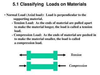
FIGURE 2.33
Off-axis loading in the x-direction
The stresses in the local axes are:
The strains in the local axes are:
Assume there is a linear relationship between all the stresses and strains till failure, then
the ultimate failure strains are:
or:
which give:
•
The strength ratio from Maximum Stress Failure Theory and
Maximum Strain Failure Theory is 16.33 MPa. There is no
difference between the two values because the mode of
failure is shear.
•
However, if the mode of failure were other than shear, there
would have been a difference between the strength ratios
due to the Poisson's ratio effect, which couples the normal
strains and stresses in the local axes.
•
Neither, the Maximum Stress Failure Theory nor the
Maximum Strain Failure Theory have any coupling between
the three possible modes of failure.
The failure theories in macromechanical analysis are based on the normal and shear strengths of a unidirectional lamina, with five strength parameters. A lamina is considered failed if certain criteria related to ultimate strain values are violated. In a specific example with a Graphite/Epoxy lamina, off-axis loading leads to stresses in local axes, and a linear relationship is assumed between stresses and strains.

Download Presentation

Please find below an Image/Link to download the presentation.
The content on the website is provided AS IS for your information and personal use only. It may not be sold, licensed, or shared on other websites without obtaining consent from the author.If you encounter any issues during the download, it is possible that the publisher has removed the file from their server.
You are allowed to download the files provided on this website for personal or commercial use, subject to the condition that they are used lawfully. All files are the property of their respective owners.
The content on the website is provided AS IS for your information and personal use only. It may not be sold, licensed, or shared on other websites without obtaining consent from the author.
E N D
Presentation Transcript
Chapter 2 MacromechanicalAnalysis of a Lamina Maximum Strain Failure Theory Dr. Autar Kaw Department of Mechanical Engineering University of South Florida, Tampa, FL 33620 Courtesy of the Textbook Mechanics of Composite Materials by Kaw
The failure theories are generally based on the normal and shear strengths of a unidirectional lamina. In the case of a unidirectional lamina, the five strength parameters are: ( )ult 1 T Longitudinal tensile strength ( )ult 1 C Longitudinal compressive strength ( )ult 2 T Transverse tensile strength ( )ult 2 C Transverse compressive strength ( )ult In-plane shear strength 12
The lamina is considered to be failed if: ( ) ( ) ( ( ) , or < ult 1 ( ) , or < ult 2 ( 12 12 < C 1 T < 1 ult C 2 T < 2 ult ) ) , ult < 12 ult is violated, where: ( )ult 1 ( )ult 1 ( )ult 2 ( )ult 2 ( )ult 12 T = Ultimate longitudinal tensile strain (in direction 1), C = Ultimate longitudinal compressive strain (in direction 1), T = Ultimate transverse tensile strain (in direction 2), = Ultimate transverse compressive strain (in direction 2), C = Ultimate in-plane shear strain (in plane 1-2).
= = = 2 , 3 , and 4 S S S Find the maximum value of S>0 if a stress of is applied to a 60o lamina of Graphite/Epoxy. Use Maximum Strain Failure Theory. Use properties of a unidirectional Graphite/Epoxy lamina given in Table 2.1 of the textbook Mechanics of Composite Materials by Autar Kaw. x y xy FIGURE 2.33 Off-axis loading in the x-direction
The stresses in the local axes are: 0 2500 0 7500 0 8660 2 . . . S 1 0 7500 0 2500 0 8660 3 = . . - . - S 2 0 4330 0 4330 0 5000 4 - . . - . S 12 1 . 1714 0 10 1 0 2714 = - . S. 10 1 0 4165 - . 10
The strains in the local axes are: 1 1 S = 2 2 12 12 10 . 1367 0 10 0 11 11 1 0 5525 . 1547 0 . 1714 0 . 10 10 10 = 9 0 2662 . S. 0 11 10 1 - . 1547 0 0 9709 0 2714 = . . S 10 10 10 10 0 0 - 9 1 . 1395 0 0 4165 . 10 10 9 0 5809 . 10
Assume there is a linear relationship between all the stresses and strains till failure, then the ultimate failure strains are: T 1 ( ) 6 1500 10 3 T 1 - ( 8 287 ult = = = . , ) 10 ult 9 181 10 E 1 C 1 ( ) 6 1500 10 3 C 1 ( 8 287 ult = = = . , ) 10 ult 9 181 10 E 1 T 2 ( ) 6 40 10 3 T 2 ( 3 883 ult = = = . , ) 10 ult 9 10 3 . 10 E 2 C 2 ( ) 6 246 10 2 C 2 ( = ) 2 388 ult = = . , 10 9 10 3 . 10 E ( 2 ) 6 68 10 12 3 ( ) 9 483 ult = = = . . 10 ult 12 9 7 . 17 10 G 12
10 . 1367 0 10 3 10 3 8 287 . 1367 0 8 287 . < S< . , 10 10 10 1 9 0 2662 = 12 . S 10 2 2 9 3 2 388 0 2662 3 883 . < . S< . , 10 10 10 - 9 0 5809 . 10 3 9 3 9 483 0 5809 9 483 . < . S< . , 10 10 10 3 T - 8 287 . ( = ult ) 10 1 or: 3 C 8 287 . ( = ) 10 1 ult 6 6 606 2 606 2 . <S< . , 10 10 3 T 3 883 . 6 6 ( = 14 58 . 89 71 . ) <S< 10 10 10 2 ult 6 6 16 33 16 33 . <S< . , 10 10 2 C 2 388 . ( = ) 10 2 ult which give: 3 9 483 . ( = ) 10 <S< 0 16 MPa. 33 . 12 ult
The strength ratio from Maximum Stress Failure Theory and Maximum Strain Failure Theory is 16.33 MPa. There is no difference between the two values because the mode of failure is shear. However, if the mode of failure were other than shear, there would have been a difference between the strength ratios due to the Poisson's ratio effect, which couples the normal strains and stresses in the local axes. Neither, the Maximum Stress Failure Theory nor the Maximum Strain Failure Theory have any coupling between the three possible modes of failure.