Hubble Space Telescope Damping System for Oscillation Reduction
This presentation focuses on the design and implementation of a compensator system to reduce deleterious oscillations affecting observations from the Hubble Space Telescope. Utilizing MATLAB for frequency response analysis, the project aims to dampen oscillations occurring at distinct frequencies, ensuring clearer observations of the Universe. Through closed-loop transfer function derivation and comparison, the effectiveness of the compensator in minimizing distortion is evaluated, highlighting its crucial role in optimizing telescope performance.
Download Presentation

Please find below an Image/Link to download the presentation.
The content on the website is provided AS IS for your information and personal use only. It may not be sold, licensed, or shared on other websites without obtaining consent from the author.If you encounter any issues during the download, it is possible that the publisher has removed the file from their server.
You are allowed to download the files provided on this website for personal or commercial use, subject to the condition that they are used lawfully. All files are the property of their respective owners.
The content on the website is provided AS IS for your information and personal use only. It may not be sold, licensed, or shared on other websites without obtaining consent from the author.
E N D
Presentation Transcript
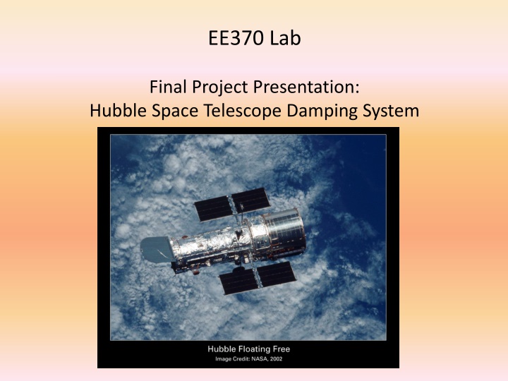
EE370 Lab Final Project Presentation: Hubble Space Telescope Damping System
This project is based on problem 10.47 from the classs textbook. transitions from darkness into sunlight, there are oscillations that occur at two distinct frequencies. These oscillations are deleterious to crisp observation of the Universe. When the Hubble telescope is on the daytime side of the Earth, or when it placed in cascade with the telescope s directional control system. The transfer function of the compensator is: A compensator is proposed to reduce the effect of these oscillations when 1.96(?2+ ? + 0.25)(?2+ 1.26? + 9.87) (?2+ 0.015? + 0.57)(?2+ 0.083? + 17.2) ??? =
Frequency Response of Compensator MATLAB is an easy way to obtain the frequency response of the compensator:
Effect of Compensator in feedback loop In order to understand how the compensator damps the frequencies of the Thermal Flutter we need to derive the closed loop transfer function to determine how the disturbance affects the output. Here is the block diagram of the system: We can derive the output in terms of the input and the feedback: Y = DGp + (R Y)GcGGp Y(1 + GcGGp) = RGcGGp+ DGp GcGGp 1 + GcGGp Gp Y = R + D 1 + GcGGp
Regardless of the specific transfer functions of the controller and plant, the large magnitude response of the compensator at the two frequencies will damp those frequencies. Two examples are presented, one with unity transfer functions for both the controller and plant, and one with: 8 125 G s = ? + 8 ??? = ?2+ ? + 125 Frequency Response 1
Frequency Response 2 (non-unity controller and plant TF)
Effect of compensator on transfer function Y(s)/R(s) Another question is how the compensator affects the closed loop transfer function Y(s)/R(s). We want to minimize distortion. We compare the frequency response of the transfer function with and without the compensator. ??? ????? 1 + ????? ? ? = and ? ? = 1 + ??? MATLAB code: >> nc = num; dc = den; >> n = [8]; d = [1 8]; np = [125]; dp = [1 10 125]; >> num1 = conv(n, np); den1 = conv(d, dp) + [0 0 0 1000]; >> num2 = conv(n, conv(np, nc)); den2=conv(conv(dc, d), dp); >> den3 = conv(nc, conv(n, np));den3=[0 0 0 den3]; >> den2 = den2+den3; tf_without = tf(num1, den1); >> tf_with = tf(num2, den2);
Without compensator With compensator
Nyquist mapping When creating a Nyquist plot, we map points along the imaginary axis through The loop transfer function, L(s). The magnitude is: ?(? ??) ?=0 L(s) = ?=0 ?(? ??),where s = j . Note that the magnitude of the mapping will increase when s approaches a pole. This will happen when s is near the poles on the imaginary axis.
Nyquist Plot of compensator transfer function When the poles of the compensator transfer function are examined it becomes apparent that they are very close to the imaginary axis. When the Nyquist Plot is generated, we can expect an increase in the magnitude of the mapping when s = j is near the poles. The below root locus shows the location of the poles.
EE370L Lessons EE370 taught the students some valuable engineering methods. The subject of control systems has fascinating applications, as demonstrated by this apropos problem. engineering requires work, as most students will admit. Unfortunately, this understanding of

![get⚡[PDF]❤ The Hubble Space Telescope: From Concept to Success (Springer Praxis](/thumb/21514/get-pdf-the-hubble-space-telescope-from-concept-to-success-springer-praxis.jpg)


