Kobelco SK27SR-5 Acera COMPACT EXCAVATOR Service Repair Manual Instant Download (Book Code No. S5PV0021E02)
Please open the website below to get the complete manualnn//
Download Presentation

Please find below an Image/Link to download the presentation.
The content on the website is provided AS IS for your information and personal use only. It may not be sold, licensed, or shared on other websites without obtaining consent from the author. Download presentation by click this link. If you encounter any issues during the download, it is possible that the publisher has removed the file from their server.
E N D
Presentation Transcript
SERVICE MANUAL Compact Hydraulic Excavator SK27SR-5 Acera S5PV0021E02 APPLICABLE: SK27SR-5 . . . . . . . . . . . . . PV13 - and higher KOBELCO CONSTRUCTION MACHINERY AMERICA, LLC. 245 E NORTH AVENUE CAROL STREAM, IL 60188 U.S.A. English Issued August 2010 Part Number S5PV0021E02 Printed in U.S.A. Rac
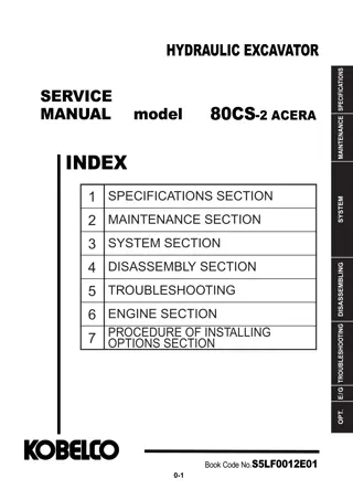
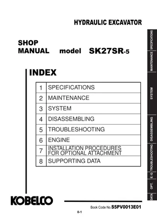
COMPACT HYDRAULIC EXCAVATOR SPECIFICATIONS SHOP MANUAL model SK27SR-5 ACERA MAINTENANCE INDEX 1 2 3 4 5 6 7 SPECIFICATIONS SECTION SYSTEM MAINTENANCE SECTION SYSTEM SECTION DISASSEMBLY SECTION DISASSEMBLING TROUBLESHOOTING ENGINE SECTION PROCEDURE OF INSTALLING OPTIONS SECTION TROUBLESHOOTING E/G OPT. Book Code No.S5PV0021E02 0-1
INDEX NA SK27SR-5 Book Code No. Distribution Year Month Index No. 1 Title 33 S5PA0105E01 2010-05 SPECIFICATIONS 1 OUTLINE S5PV0221E02 2010-06 S5PV0321E02 2010-06 S5PV1121E02 2010-06 S5PV1221E02 2010-06 S5PV1321E02 2010-06 _ 2 SPECIFICATIONS 3 ATTACHMENT DIMENSIONS 2 34 42 MAINTENANCE 11 TOOLS STANDARD MAINTENANCE TIME SCHEDULE MAINTENANCE STANDARD AND TEST PROCEDURE 12 13 3 11 43 51 S5PV2221E02 2010-06 S5PV2321E02 2010-06 S5PV2421E02 2010-06 _ 22 HYDRAULIC SYSTEM SYSTEM 23 ELECTRIC SYSTEM 12 44 24 COMPONENTS SYSTEM _ 13 GENERAL DISASSEMBLY & ASSEMBLY S5PA3105E01 2010-05 S5PV3221E02 2010-06 S5PV3321E02 2010-06 S5PV3421E02 2010-06 31 DISASSEMBLING 32 ATTACHMENT UPPER SLEWING STRUCTURE 33 22 34 TRAVEL SYSTEM _ TROUBLESHOOTING S5PW4231E02 2010-06 S5PW4331E02 2010-06 S5PW4431E02 2010-06 S5PV5121E02 2010-06 _ 42 HYDRAULIC SYSTEM 23 31 43 ELECTRICAL SYSTEM 44 ENGINE E/G 51 ENGINE 24 32 _ _ PV13~ APPLICABLE MACHINES 0-5
https://www.ebooklibonline.com Hello dear friend! Thank you very much for reading. Enter the link into your browser. The full manual is available for immediate download. https://www.ebooklibonline.com
NOTE: Any modification or adaptation which is not approved by the manufacturer may invalidate the machine s initial conformity with safety requirements and warranty. This Manual is prepared as technical material contain- ing the information necessary for the maintenance and repairing services of hydraulic excavators. The materi- al is categorized into 7 Chapters, Specification, Mainte- nance, System, Disassembly, Troubleshooting, Engine, and Installation Procedures for Optional At- tachment. The information in this manual is provided on the basis of information that was available at the time the manual was written. Settings, procedures, part numbers, soft- ware and other items can change. These changes can affect the service that is given to the machine. Ensure that you have complete and current information before you start any machine operation The Chapter "Specification" describes the specifi- cations for entire machine and material. It contains information for attachment replacement and repair. The Chapter "Maintenance" describes the materi- al, which is helpful for maintenance service and ad- justments for entire machine. ATTENTION: The engine and fuel system on your ma- chine is designed and built to government emissions standards. Tampering by dealer, customers, operators and users is strictly prohibited by law. Failure to comply could result in government fines, rework charges, in- valid warranty, legal action, and possible confiscation of the machine until rework to original condition is com- pleted. Engine service and/or repairs must be done by a certified technician only. The Chapter "System" describes the operating sys- tems. It contains information for the hydraulic sys- tem, electric system, components, etc. The Chapter "Disassembly" describes the removal and installing of assembly mounted on the upper structure and undercarriage, and the assembling and disassembling of the associated hydraulic equipment. The Chapter "Troubleshooting" describes common faults and repair guidelines. The Chapter "Engine" describes the engine and the usage of the "Maintenance Manual" provided by the engine manufacturer. The Chapter "Installation Procedures for Optional Attachment" describes the equipment added by customer request. 0-6
1. OUTLINE 1 1. OUTLINE TABLE OF CONTENTS 1.1 GENERAL PRECAUTIONS FOR REPAIRS ........................................................1-3 1.1.1 PREPARATION BEFORE DISASSEMBLING ..............................................1-3 1.1.2 SAFETY IN DISASSEMBLING AND ASSEMBLING ...................................1-3 1.1.3 DISASSEMBLING AND ASSEMBLING HYDRAULIC EQUIPMENT ..........1-5 1.1.4 ELECTRICAL EQUIPMENT ........................................................................1-7 1.1.5 HYDRAULIC PARTS ....................................................................................1-8 1.1.6 WELDING REPAIR ......................................................................................1-8 1.1.7 ENVIRONMENTAL MEASURES .................................................................1-8 1.2 INTERNATIONAL UNIT CONVERSION SYSTEM (Based on MARKS' STANDARD HANDBOOK FOR MECHANICAL ENGINEERS) ................................................1-9 Book Code No. S5PA0105E01 1-1
1. OUTLINE Issue Date of Issue Applicable Machines Remarks S5PA0105E01 (NHK-EUR) First Edition June, 2009 E10SR : PA03-05001~ (CASE-AUS) February, 2010 CX50B : PJ06-08001~ (NH-AUS) E50B : PJ06-08001~ (KCM S.E.ASIA&OCE) SK20SR-5 : PM10-10001~ SK27SR-5 : PV13-33001~ (KCM North America) SK30SR-5 : PW14-46519~ SK35SR-5 : PX15-21105~ March, 2010 (CASE-NA) CX31B : PW14-46519~ CX36B : PX15-21105~ (NH-NA) E30B : PW14-46519~ E35B : PX15-21105~ (CASE-NA) CX27B : PV13-33292~ (NH-NA) E27B : PV13-33292~ (KCM North America) April, 2010 SK50SR-5 : PJ06-09807~ (CASE-NA) CX50B : PJ06-09807~ (NH-NA) E50B : PJ06-09807~ (KCM S.E.ASIA&OCE) SK30SR-5 : PW14-46519~ SK35SR-5 : PX15-21105~ (CASE-AUS) CX31B : PW14-46519~ CX36B : PX15-21105~ (NH-AUS) E30B : PW14-46519~ E35B : PX15-21105~ (CASE-Australia) CX27B : PV13-33001~ (NH-AUS) E27B : PV13-33001~ (KCM S.E.ASIA&OCE) SK40SR-5 : PH07-06609~ SK50SR-5 : PJ06-09807~ May, 2010 (NH-AUS) E50B : PJ06-09807~ (CASE-AUS) CX50B : PJ06-09807~ (NA) SK27SR-5 : PV13-33453~ (CASE-NA) CX27B : PV13-33453~ (NH-NA) E27B : PV13-33453~ 1-2
1. OUTLINE 1.1 GENERAL REPAIR SAFETY 1 1.1.1 PREPARATION BEFORE DISASSEMBLING Read Operator's Manual before disassembling (1) UNDERSTAND THE OPERATING PROCEDURE Read the OPERATOR'S MANUAL carefully to understand the operating procedure. (2) CLEAN THE MACHINE Remove soil, mud, and dust from the machine before servicing. This will allow better visibility of components and lessen contamination issues. (3) INSPECTION Identify the components to be serviced. Make note of surrounds (i.e. repair facility or field repair). Request all ser- vice parts prior to servicing. (4) RECORDING Make note and record: 1. Inspection date and place. 2. Model name, applicable machine number, and hour meter read. 3. Repair issue, place and cause. 4. Visible oil leakage, water leakage and damage. 5. Clogging of filters, oil level, oil quality, oil contamination and loosening of connections. 6. Note if problem exists based on the operation rate per month calculated from hour meter indication after the previous inspection date. (5) WORKING CONDITIONS AND REQUIREMENTS 1. Tools required for repair work. 2. Prepare space to place the disassembled parts. 3. Prepare oil containers for draining oil etc. 1.1.2 SAFETY IN DISASSEMBLING AND ASSEMBLING WARNING Avoid injury! The safety alert symbol is used to alert you to potential personal injury hazards. Carefully read and observe all the precautionary advice contained in this manual. Failure to comply could result in death or serious injury. W0044A (1) Be prepared for emergencies. Always have a first aid kit and a working fire extinguisher with you and know how to use each.Wear appropriate clothes with long sleeves, safety shoes, safety helmet and protective glasses. (2) Avoid loose fitting clothing, loose or uncovered long hair, jewelry. (3) Use the correct protective equipment when servicing this machine. Hard hats, protective glasses, protective shoes, gloves, reflector type vests, respirators and ear protection are examples of the type of equipment that may be required (4) Do not attempt maintenance work if you have not had the appropriate training or doubt your ability to perform the required service. (5) Read the repair procedure completely before starting any service or maintenance task. 1-3
1. OUTLINE (6)Before beginning any inspection or maintenance procedures, secure a DO NOT OPERATE tag to the opera- tor s console to inform the operator that the machine will be inoperable for inspection and maintenance. This tag will prevent accidental starting of the machine. (7)Disconnect the battery before working on the electrical system. Know the consequences of disconnecting any electronic or computer devices. (8)Avoid lubrication or mechanical adjustments with the machine in motion or the engine operating. If the engine must be in operation to make certain adjustments, place the transmission in neutral, apply the parking brake, place the equipment in a safe position, securely block the tracks and use extreme caution. (9)Securely block the machine or any component that may fall before working on the machine or component. If possible, use a back up or secondary blocking device, also. (10)To prevent unexpected movement, securely block working elements when repairing or changing working tool parts such as cutting edges. (11)Never make repairs on pressurized components, fluid, gas or mechanical until the pressure has been relieved according to the manufacturer s instructions. (12)Use extreme caution when removing radiator caps, drain plugs, grease fittings or pressure taps. Park the machine and let it cool down before opening a pressurized tank. (13)Release all pressure before working on systems which have an accumulator. Use a piece of cardboard, news- paper, or wood to check for pressurized leaks to prevent fluid penetrating the skin. Pressurize accumulators with the proper gas according to manufacturer s recommendations. (14)When absolutely necessary to tow the machine, do not exceed the recommended towing speed. Be sure the towing machine has sufficient braking capacity to stop the towed load. If the towed machine cannot be braked, a tow bar must be used or two towing machines must be used. - one in front pulling and one in the rear to act as a brake. Avoid towing over long distances. (15)Observe proper maintenance procedures. (16)Whenever servicing or replacing hardened pins, etc., use a brass drift or other suitable material between the hammer and pin. Alternate: Use a brass hammer, drift or suitable material on the pin, etc. (17)Keep the brakes and steering systems in good operating condition. (18)Replace all missing, illegible or damaged safety signs. Keep all safety signs clean. (19)Use proper tools, and replace or repair defective tools. (20)Support the machine and attachment with supports or blocks if the work must be performed in a lift condition. 1-4
1. OUTLINE 1.1.3 DISASSEMBLING AND ASSEMBLING HYDRAULIC EQUIPMENT 1 (1) REMOVING HYDRAULIC EQUIPMENT 1. Before disconnecting any hydraulic line, fitting, disconnect, release the hydraulic pressure in the system. 2. Clean the exterior surface of the equipment before disassembling,. 3. Carefully drain oil from the hydraulic lines into clean, uncontaminated containers.. 4. Apply plugs or caps on the line ends to avoid oil spillage and contaminationn. (2) DISASSEMBLING HYDRAULIC EQUIPMENT 1. Do not disassemble, reassemble or modify the hydraulic equipment without the permission of the manufacturer. The manufacturer will not be responsible for the performance and function of the product after unauthorized modification. Such modifications may void the equipment warranty. 2. Use matching marks to facilitate reassembling work. 3. Before starting the work, read the disassembly procedure, and determine if work can be completed correctly by service personnel. 4. Use the special jig and tools when specified. 5. Place the removed parts in order and attach tags to facilitate reassembly. 6. Note the location and quantity of parts commonly applied to multiple locations. (3) INSPECTING PARTS 1. Ensure that the disassembled parts are free from seizure, interference and uneven contact. 2. Measure and record wear condition of parts and clearance. 3. If the problem is found in a part, repair or replace it with a new one. (4) REASSEMBLING HYDRAULIC EQUIPMent 1. When cleaning parts, make certain ventilation is adequate. Wear a breathing mask if necessary. 2. Perform rough and finish cleaning before assembling. 3. Remove washing oil with air and apply clean hydraulic or gear oil for assembling. 4. Always replace the removed O-rings, backup rings and oil seals with new ones. 5. Remove dirt and moisture and degrease the surface where liquid gasket to be applied. 6. Remove rust preventive agent from the new parts before use. 7. Fit bearings, bushings and oil seals using special jigs. 8. Assemble the parts utilizing matching marks. 9. Ensure all the parts are completely assembled. 1-5
1. OUTLINE (5) INSTALLING hydraulic equipment 1. Ensure hydraulic oil and lubricant are properly supplied. 2. Perform air bleeding when : a. Hydraulic oil changed b. Parts of suction side piping replaced c. Hydraulic pump installed d. Swing motor installed e. Travel motor installed f. Hydraulic cylinder installed 3. Perform air bleeding of the hydraulic pump and swing motor after loosening the upper drain plug, starting the engine. Keep the engine at low idle. Complete the air bleeding when seeping of hydraulic oil is apparent, and tightly plug. 4. Perform air bleed of the travel motor and the hydraulic cylinders by running the engine for more than 5 minutes at low speed without load. 5. Perform air bleeding of pilot line by performing a series of digging, slewing and travel. 6. Check hydraulic oil level after placing the attachment in the oil check position, and replenish oil if necessary. Level gauge Oil level lines (Level located between the two lines shows appropriate amount of oil) NOTICE:Always make certain the machine has the correct hydraulic oil and always bleed air from the hydraulic system. Operating the equipment without oil or with air in the lines can result in damage to the machine. NOTICE: Do not allow the hydraulic cylinder to bottom on the stroke end immediately after maintenance. 1-6
1. OUTLINE 1.1.4 ELECTRICAL EQUIPMENT 1 WARNING BATTERY ACID CAUSES SEVERE BURNS. Batteries contain sulfuric acid. Avoid contact with skin, eyes or clothing. Antidote: EXTERNAL - Flush with water. Antidote: INTERNAL - Drink large quantities of water or milk. DO NOT induce vomiting. Seek medical attention immediately. EYES - Flush with water for 15 minutes and seek medical attention immediately. M111A WARNING Explosive gas! Batteries emit explosive hydrogen gas and other fumes while charging. Ventilate the charging area. Keep the battery away from sparks, open flames, and other ignition sources. Never charge a frozen battery. Failure to comply could result in death or serious injury. W005A (1) Disconnect battery before performing any electrical repairs. (2) Handle batteries carefully. (3) Turn the key OFF prior to connecting and disconnecting battery. (4) Disconnect electrical connectors by holding and pressing the lock. Do not pull the wire to apply force. (5) Connect the connector and ensure it is completely locked. (6) Turn the key OFF prior to touching the terminal of starter or generator. (7) Remove the ground (earth) terminal of battery when handling tools around the battery or its relay. (8) Do not splash water on the electrical equipment and connectors when cleaning the machine or components. (9) Check for moisture adhesion inside waterproof connector after removal. If moisture adhesion is found, dry it completely with low pressure air before the connection. 1-7
1. OUTLINE 1.1.5 HYDRAULIC PARTS (1) O-RING Ensure O-rings have elasticity and are not damaged. Use the appropriate O-rings. O-rings are made of various kinds of materials and have a variety of compositions in order to adhere to a variety of parts. Always use O-rings designed specifically for component being repaired. Fit the O-rings without distortion and/or wrinkles or folds. Always replace floating seals as a pair. (2) Flexible hose (F hose) Use the appropriate parts. Different parts are used depending on the working pressure even if the size of fitting and the total length of the hose is same. Tighten the fitting to the specified torque. Make certain there is no kink, tension, interference nor oil leakage from hose. 1.1.6 WELDING REPAIR (1)Refer repair welding to qualified personnel according to the appropriate procedure. (2)Disconnect the ground (earth) cable of the battery before starting the repair. Failure to do so will cause damage to the electrical equipment. (3)Do not weld near flammable materials. (4)Before starting the repair of the attachment, do not fail to cover the plated surface of the piston rod with a flameproof shield to prevent it from being exposed to sparks. 1.1.7 ENVIRONMENTAL MEASURES (1)Engine exhaust fumes can cause death or serious injury. If necessary to run the engine, make certain there is adequate ventilation. (2)Waste disposal Dispose of the following parts according to the relevant regulations : Waste oil and waste container Battery (3)High pressure fluids High pressure fluid can penetrate the skin and cause serious injury. Search for leaks with a piece of cardboard. Protect hands and body from high-pressure fluids. If an injury occurs, seek medical treatment immediately. Any fluid injected into the skin must be surgically removed or gangrene may develop. (4)Precautions for handling hydraulic oil Exposure of eyes to hydraulic oil will cause inflammation. Wear protective safety glasses before handling to avoid an accident. If an eye is exposed to the oil, take the following emergency measures : -When an eye exposed : Immediately flood with water. -When swallowed : Do not induce vomiting, seek medical treatment immediately. -When skin exposed: Wash with water and soap. (5)Others Use replacement parts and lubricants authorized as the manufacturer's genuine parts. 1-8
1. OUTLINE 1.2 INTERNATIONAL UNIT CONVERSION SYSTEM (Based on MARKS' STANDARD HANDBOOK FOR MECHANICAL ENGINEERS) 1 Base units Table 1-1 This manual includes International System of Unit and Foot-Pound System of Units, if you need SI unit, refer to the following international system of units. Units that are related to this manual: 1. Etymology of SI Unites French: Le Systeme International d' Unites English: International System of Units 2. Construction of SI Unit System Derived units of base units Table 1-3 Supplemen tary units Table 1-2 SI units SI unit system Derived units bearing peculiar designations Table 1-4 Derived units Prefixes of SI (n-th power of 10, where n is an integer) Table 1- 5 (4) Derived Units bearing Peculiar Designations (1) Base units Table 1-4 Table 1-1 QUANTITY Frequency Force Pressure and Stress Energy, Work and Quantity of heat Power Quantity of electricity Electric potential difference, Voltage, and Electromotive force Quantity of static electricity and Electric capacitance Electric resistance UNIT SYMBOL Hz N FORMULA 1/s kg m/s 2 QUANTITY Length Mass Time Electric current Thermodynamic temperature Amount of substance Luminous intensity UNIT SYMBOL m kg s A hertz newton meter kilogram second ampere pascal Pa N/m2 kelvin K joule J N m mol mol watt W J/s coulomb C A s candela cd (2) Supplementary units Table 1-2 volt V W/A QUANTITY Plane angle Solid angle UNIT SYMBOL rad sr radian steradian farad F C/V (3) Derived Units Table 1-3 QUANTITY Area Volume Velocity Acceleration meter per second squared Density kilogram per cubic meter UNIT SYMBOL m2 m3 m/s m/s2 kg/m3 ohm V/A square meter cubic meter meter per second celcius degree or degree lux Celcius temperature (t+273.15)K C Illuminance lx l m/m2 1-9
1. OUTLINE (6) Unit Conversion (5) Prefixes of SI Table 1-6 Table 1-5 QUANTITY Gravitational SI Mass Force Torque Pressure Motive Power Revolution CONVERSION FACTOR PREFIX giga mega kilo hecto deca deci centi milli micro nano pico SYMBOL G M k h da d c m n p MULTIPLICATION FACTORS 109 106 103 102 10 10 1 10 2 10 3 10 6 10 9 10 12 kg kgf kgf m kgf/cm2 kg N N m kgf m=9.807 N m MPa 1 kgf/cm2=0.09807 MPa 1 kgf=9.807 N PS kW 1 PS=0.7355 kW rpm min 1r/min *1 *1 Units that are allowed to use. 1-10
2. SPECIFICATIONS 2 2. SPECIFICATIONS TABLE OF CONTENTS 2.1 2.2 2.3 2.4 2.5 2.6 2.7 2.8 COMPONENT LOCATION ...................................................................................2-3 MACHINE DIMENSIONS .....................................................................................2-4 SPECIFICATIONS AND PERFORMANCE ..........................................................2-5 MACHINE & COMPONENTS WEIGHT (DRY) ....................................................2-7 TRANSPORTATION .............................................................................................2-9 TYPE OF CRAWLER SHOES .............................................................................2-12 TYPE OF BUCKET ..............................................................................................2-13 ENGINE SPECIFICATIONS .................................................................................2-14 2.8.1 SPECIFICATIONS .......................................................................................2-14 2.8.2 ENGINE PERFORMANCE CURVE .............................................................2-15 Book Code No. S5PV0221E02 2-1
2. SPECIFICATIONS Issue Date of Issue Applicable Machines Remarks S5PV0221E01 (NA) First Edition May, 2010 SK27SR-5 : PV13- S5PV0221E02 (NA) Revision June, 2010 SK27SR-5 : PV13-33453~ 2-2
2. SPECIFICATIONS 2.1 COMPONENT LOCATION ARM CYLINDER BOOM BOOM CYLINDER BUCKET CYLINDER CANOPY OPERATING LEVER DOZER OPERATING LEVER 2 ARM HYDRAULIC TANK LINK THROTTLE LEVER LIGHT CONTROL VALVE BUCKET MONITOR PANEL (GAUGE CLUSTER) TRAVEL LEVER SAFETY LOCK LEVER RADIATOR AIR CLEANER SWING CYLINDER RESERVOIR TANK DOZER CYLINDER MUFFLER BATTERY ENGINE FUEL TANK DOZER RUBBER CRAWLER SHOE IDLER ASSY LOWER ROLLER OIL FILTER UPPER ROLLER SLEWING MOTOR SWIVEL JOINT HYDRAULIC PUMP SLEWING BEARING TRAVEL MOTOR 2-3
2. SPECIFICATIONS 2.2 MACHINE DIMENSIONS (1) SK27SR-5 (CANOPY) Unit: mm (ft-in) 170(6.7") 555 (1'9.9") 1500 (4'11.1") R750 (2'5.5") 610 (2'0.0") (3.5") 90 (1.8") 45 4130 (13'6.6") 1720 (5'7.7") 1360 (4'5.5") 1400 (4'7.1") 750 (2'5.5") 2500 (8'2.4") (13.6") (13.6") (11.8") 345 345 345 300 345 250 (9.8") (1'8.5") 520 1440 (4'8.7") 1590 (5'2.6") 250 (9.8") 1250 (4'1.2") 1500 (4'11.1") 1980 (6'6.0") 2410 (7'10.9") (2) SK27SR-5 (CAB) 170(6.7") 555 (1'9.9") 610 (2'0.0") 1500 (4'11.1") R750 (2'5.5") (3.5") 90 (1.8") 45 4130 (13'6.6") 1720 (5'7.7") 1360 (4'5.5") 1400 (4'7.1") 750 (2'5.5") 2500 (8'2.4") (11.8") 345 345 300 250 (9.8") (1'8.5") 520 1440 (4'8.7") 1590 (5'2.6") 250 (9.8") 1250 (4'1.2") 1500 (4'11.1") 1980 (6'6.0") 2410 (7'10.9") 2-4
Suggest: For more complete manuals. Please go to the home page. https://www.ebooklibonline.com If the above button click is invalid. Please download this document first, and then click the above link to download the complete manual. Thank you so much for reading
2. SPECIFICATIONS 2.3 SPECIFICATIONS AND PERFORMANCE SPEED AND GRADEABILITY Model SK27SR-5 Applicable Machines PV13-33453~ Shoe Type Rubber shoe Iron shoe (OPT) 2 min-1 {rpm} Slewing Speed 8.7 (8.7) Low (1st) High (2nd) Low (1st) High (2nd) Travel Speed km/h (mph) 2.3 4.0 2.3 4.0 Gradeability % (degree) 58(30) ENGINE Model (YANMAR) 3TNV82A-SYB Type Water-cooled, 4-cycle type Swirl chamber type diesel engine Number of cylinders-Bore X Stroke 3 - 82 dia. mm X 84 mm (3.23 in X 3.31 in) Total Displacement L 1.330 (81.2 cu-in) kW/min-1 {PS/rpm} Output Rating 15.9/2,200 (21.6/2,200) Intermediate Torque (Net) N-m/min-1 (lbf-ft/rpm) 79.0~86.0/1,320 100 (58.3~63.4/1,320 100) Starting Motor V X kW 12 X 1.7 Generator V X A 12 X 40 HYDRAULIC COMPONENTS Hydraulic Pump Variable displacement axial piston + gear pump Hydraulic Motor Axial piston Hydraulic Motor w/Reducer (Travel) 2-Axial piston, 2-Speed motor Control Valve 10-spool multiple control valve Cylinder (Boom, Arm, Swing, Bucket, Dozer) Double action cylinder Safety valve containing/Filter Type (30 ) Return Filter SIDE DIGGING & DOZER Type Boom swing by hydraulic cylinder Right 55 degrees Boom Swing Angle Left 60 degrees Stroke of Dozer (above/below) mm (in) 445 / 335 (17.5/13.2) 2-5
2. SPECIFICATIONS WEIGHT Rubber shoe Iron shoe Machine Weight kg (lb) 2,490 (5490) 2,620 (5780) Upper slewing body kg (lb) 1,310 (2890) <-- Travel system kg (lb) 830 (1830) 960 (2120) Attachment (Boom+STD Arm+STD Bucket) kg (lb) 300 (660) Oil & Water kg (lb) 50 (110) This figure is calculated with standard bucket. 2-6
https://www.ebooklibonline.com Hello dear friend! Thank you very much for reading. Enter the link into your browser. The full manual is available for immediate download. https://www.ebooklibonline.com


