Kobelco NEF Tier 4a Engine Service Repair Manual Instant Download (Book Code No. 84586860)
Please open the website below to get the complete manualnn//
Download Presentation

Please find below an Image/Link to download the presentation.
The content on the website is provided AS IS for your information and personal use only. It may not be sold, licensed, or shared on other websites without obtaining consent from the author. Download presentation by click this link. If you encounter any issues during the download, it is possible that the publisher has removed the file from their server.
E N D
Presentation Transcript
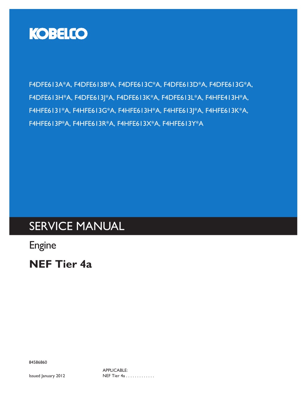
F4DFE613A*A, F4DFE613B*A, F4DFE613C*A, F4DFE613D*A, F4DFE613G*A, F4DFE613H*A, F4DFE613J*A, F4DFE613K*A, F4DFE613L*A, F4HFE413H*A, F4HFE6131*A, F4HFE613G*A, F4HFE613H*A, F4HFE613J*A, F4HFE613K*A, F4HFE613P*A, F4HFE613R*A, F4HFE613X*A, F4HFE613Y*A SERVICE MANUAL Engine NEF Tier 4a 84586860 APPLICABLE: NEF Tier 4a . . . . . . . . . . . . . KOBELCO CONSTRUCTION MACHINERY AMERICA, LLC. 245 E NORTH AVENUE CAROL STREAM, IL 60188 U.S.A. English Issued January 2012 Part Number 84586860 Printed in U.S.A. Rac
Contents INTRODUCTION HYDRAULIC, PNEUMATIC, ELECTRICAL, ELECTRONIC SYSTEMS A ELECTRICAL POWER SYSTEM ........................................................ A.30.A ENGINE AND PTO IN................................................................... B ENGINE .................................................................................. B.10.A FUEL AND INJECTION SYSTEM........................................................ B.20.A AIR INTAKE SYSTEM.................................................................... B.30.A EXHAUST SYSTEM...................................................................... B.40.A ENGINE COOLANT SYSTEM ........................................................... B.50.A EXHAUST SYSTEM Emissions control .................................................. B.40.B LUBRICATION SYSTEM ................................................................. B.60.A STARTING SYSTEM ..................................................................... B.80.A 84586860 20/01/2012
INTRODUCTION 84586860 20/01/2012 1
https://www.ebooklibonline.com Hello dear friend! Thank you very much for reading. Enter the link into your browser. The full manual is available for immediate download. https://www.ebooklibonline.com
Contents INTRODUCTION Foreword - Ecology and the environment ......................................................3 Safety rules .....................................................................................4 Torque ..........................................................................................5 Basic instructions - Important notice regarding equipment servicing ...........................8 Basic instructions - How To Use and Navigate Through This Manual ..........................9 Basic instructions - Shop and Assembly ...................................................... 14 Torque - Minimum tightening torques for normal assembly ................................... 16 84586860 20/01/2012 2
INTRODUCTION Foreword - Ecology and the environment Soil, air, and water are vital factors of agriculture and life in general. When legislation does not yet rule the treatment of some of the substances which are required by advanced technology, sound judgement should govern the use and disposal of products of a chemical and petrochemical nature. NOTICE: The following are recommendations which may be of assistance: Become acquainted with and ensure that you understand the relative legislation applicable to your country. Where no legislation exists, obtain information from suppliers of oils, filters, batteries, fuels, antifreeze, cleaning agents, etc., with regard to their effect on man and nature and how to safely store, use and dispose of these substances. Agricultural consultants will, in many cases, be able to help you as well. HELPFUL HINTS Avoid filling tanks using cans or inappropriate pressurized fuel delivery systems which may cause considerable spillage. In general, avoid skin contact with all fuels, oils, acids, solvents, etc. Most of them contain substances which may be harmful to your health. Modern oils contain additives. Do not burn contaminated fuels and or waste oils in ordinary heating systems. Avoid spillage when draining off used engine coolant mixtures, engine, gearbox and hydraulic oils, brake fluids, etc. Do not mix drained brake fluids or fuels with lubricants. Store them safely until they can be disposed of in a proper way to comply with local legislation and available resources. Modern coolant mixtures, i.e. antifreeze and other additives, should be replaced every two years. They should not be allowed to get into the soil but should be collected and disposed of properly. Do not open the air-conditioning system yourself. It contains gases which should not be released into the at- mosphere. Your CNH dealer or air conditioning specialist has a special extractor for this purpose and will have to recharge the system properly. Repair any leaks or defects in the engine cooling or hydraulic system immediately. Do not increase the pressure in a pressurized circuit as this may lead to a component failure. Protect hoses during welding as penetrating weld splatter may burn a hole or weaken them, allowing the loss of oils, coolant, etc. 84586860 20/01/2012 3
INTRODUCTION Safety rules Personal safety This is the safety alert symbol. It is used to alert you to potential personal injury hazards. Obey all safety messages that follow this symbol to avoid possible death or injury. Throughout this manual and on machine decals, you will find the signal words DANGER, WARNING, and CAUTION followed by special instructions. These precautions are intended for the personal safety of you and those working with you. Read and understand all the safety messages in this manual before you operate or service the machine. DANGER indicates a hazardous situation which, if not avoided, will result in death or serious injury. The color associated with DANGER is RED. WARNING indicates a hazardous situation which, if not avoided, could result in death or serious injury. The color associated with WARNING is ORANGE. CAUTION, used with the safety alert symbol, indicates a hazardous situation which, if not avoided, could result in minor or moderate injury. The color associated with CAUTION is YELLOW. FAILURE TO FOLLOW DANGER, WARNING, AND CAUTION MESSAGES COULD RESULT IN DEATH OR SERIOUS INJURY. Machine safety NOTICE: Notice indicates a situation which, if not avoided, could result in machine or property damage. The color associated with Notice is BLUE. Throughout this manual you will find the signal word Notice followed by special instructions to prevent machine or property damage. The word Notice is used to address practices not related to personal safety. Information NOTE: Note indicates additional information which clarifies steps, procedures, or other information in this manual. Throughout this manual you will find the word Note followed by additional information about a step, procedure, or other information in the manual. The word Note is not intended to address personal safety or property damage. 84586860 20/01/2012 4
INTRODUCTION Torque Component Size Specification Cylinder Head and Components Plug " " " M6 Nut M8 Screw 10 - 14 Nm (7.4 - 10.3 lb ft) 20 - 28 Nm (14.8 - 20.7 lb ft) 31 - 41 Nm (22.9 - 30.2 lb ft) 6 - 10 Nm (4.4 - 7.4 lb ft) 20 - 28 Nm (14.8 - 20.7 lb ft) Grid Heater Intake Manifold Engine Lifting Bracket Rear Front Cylinder Head First Phase Second Phase Third Phase Cylinder Head First Phase Second Phase Third Phase Rocker Bracket Rocker Arm Jam Nuts Exhaust Manifold Valve Cover Turbocharger 6 Cylinder M12 M8 M12x1.75x130 mm 65 - 89 Nm (47.9 - 65.6 lb ft) 20 - 28 Nm (14.8 - 20.7 lb ft) 30 - 40 Nm (22.1 - 29.5 lb ft) 85 - 95 85 - 95 M12x1.75x150 mm 50 - 60 Nm (36.9 - 44.3 lb ft) 85 - 95 85 - 95 31 - 41 Nm (22.9 - 30.2 lb ft) 20 - 28 Nm (14.8 - 20.7 lb ft) 48 - 58 Nm (35.4 - 42.8 lb ft) 20 - 28 Nm (14.8 - 20.7 lb ft) M8 Nut M8 Screw M8 Nut M8 Screw M8 Nut 6 - 8 Nm (4.4 - 5.9 lb ft) 37 - 49 Nm (27.3 - 36.1 lb ft) 6 - 8 Nm (4.4 - 5.9 lb ft) 20 - 28 Nm (14.8 - 20.7 lb ft) 4 Cylinder Front Case Front Cover Rear Case Gear Case M8 Screw 20 - 28 Nm (14.8 - 20.7 lb ft) M12 Screw M10 Screw M8 Screw M10 M12 65 - 89 Nm (47.9 - 65.6 lb ft) 42 - 52 Nm (31.0 - 38.4 lb ft) 20 - 28 Nm (14.8 - 20.7 lb ft) 75 - 95 Nm (55.3 - 70.1 lb ft) 44 - 54 Nm (32.5 - 39.8 lb ft) Flywheel Housing Cylinder Block and Crankshaft Components Camshaft Retaining Plate Camshaft Gear Crankcase Plate Vibration Damper and Adapter First Phase Second Phase Drive Pulley Engine Flywheel First Phase Second Phase Main Caps First Phase Second Phase Third Phase Connecting Rod Caps First Phase Second Phase M8 Screw M8 Screw M10 Screw M12 20 - 28 Nm (14.8 - 20.7 lb ft) 32 - 40 Nm (23.6 - 29.5 lb ft) 38 - 48 Nm (28.0 - 35.4 lb ft) 45 - 55 Nm (33.2 - 40.6 lb ft) 90 61 - 75 Nm (45.0 - 55.3 lb ft) M10 M12 26 - 34 Nm (19.2 - 25.1 lb ft) 55 - 65 M12 44 - 56 Nm (32.5 - 41.3 lb ft) 74 - 86 Nm (54.6 - 63.4 lb ft) 85 - 95 55 - 65 Nm (40.6 - 47.9 lb ft) 55 - 65 84586860 20/01/2012 5
INTRODUCTION Component Size Specification Lubrication System and Components Oil Pump First Phase Second Phase Oil Pressure Relief Valve Oil Cooler and Oil Filter Base Oil Filter Connection on Filter Base for Turbo Oil Supply Turbo Lubrication Pipe Turbo Lubrication Pipe Adapter Oil Pan Piston Spray Nozzles Electrical Components Camshaft Sensor M8 M8 M22 M8 Screw 7 - 9 Nm (5.2 - 6.6 lb ft) 20 - 28 Nm (14.8 - 20.7 lb ft) 72 - 88 Nm (53.1 - 64.9 lb ft) 20 - 28 Nm (14.8 - 20.7 lb ft) Contact + Turn 20 - 28 Nm (14.8 - 20.7 lb ft) 1 " M12 Nut M12 8 - 12 Nm (5.9 - 8.9 lb ft) 30 - 40 Nm (22.1 - 29.5 lb ft) 20 - 28 Nm (14.8 - 20.7 lb ft) 12 - 18 Nm (8.9 - 13.3 lb ft) M8 M6 Studs M6 Nut M6 Screw M6 Screw M8 Screw 6 - 10 Nm (4.4 - 7.4 lb ft) 8 - 12 Nm (5.9 - 8.9 lb ft) 6 - 10 Nm (4.4 - 7.4 lb ft) 8 - 12 Nm (5.9 - 8.9 lb ft) 20 - 28 Nm (14.8 - 20.7 lb ft) 1.25 - 1.75 Nm (0.92 - 1.29 lb ft) 8 - 12 Nm (5.9 - 8.9 lb ft) 20 - 28 Nm (14.8 - 20.7 lb ft) 10 - 14 Nm (7.4 - 10.3 lb ft) 10 - 14 Nm (7.4 - 10.3 lb ft) 6 - 10 Nm (4.4 - 7.4 lb ft) 17 - 23 Nm (12.5 - 17.0 lb ft) 5 - 7 Nm (3.7 - 5.2 lb ft) 30 - 40 Nm (22.1 - 29.5 lb ft) 17 - 23 Nm (12.5 - 17.0 lb ft) 5 - 7 Nm (3.7 - 5.2 lb ft) 10 - 14 Nm (7.4 - 10.3 lb ft) 37 - 49 Nm (27.3 - 36.1 lb ft) 37 - 49 Nm (27.3 - 36.1 lb ft) 37 - 49 Nm (27.3 - 36.1 lb ft) Wiring Bulkhead Support Bracket for Injector Wiring Injector Wiring ECU Cooling Plate M6 Screw M8 Screw M12 M12 M6 Screw M14 Screw M5 Screw Fuel Outlet Fuel Inlet Crankshaft Speed Sensor Coolant Temperature Sensor Oil Pressure / Temperature Sensor Fuel Pressure Sensor Fuel Temperature Sensor Air Pressure / Temperature Sensor Engine Oil Level Sensor Alternator Support Bracket Alternator Tension Bracket Starter Fuel System and Components Feed Pump High Pressure Pump Gear Fuel Pump Injector First Phase Second Phase Injector Feed Connector Common Rail High Pressure Fuel Line High Pressure Pipe Connector Fuel Filter Bracket Fuel Filter Holder Fuel Filter Cooling System and Components M14 M12 M10 Screw M10 Screw M8 Studs M18 Nut M8 Nut 10 - 14 Nm (7.4 - 10.3 lb ft) 100 - 110 Nm (73.8 - 81.1 lb ft) 20 - 28 Nm (14.8 - 20.7 lb ft) M6 Screw M6 Screw 8.15 - 8.85 Nm (6.0 - 6.5 lb ft) 70 - 80 45 - 55 Nm (33.2 - 40.6 lb ft) 20 - 28 Nm (14.8 - 20.7 lb ft) 18 - 22 Nm (13.3 - 16.2 lb ft) 20 - 28 Nm (14.8 - 20.7 lb ft) 71 - 85 Nm (52.4 - 62.7 lb ft) 20 - 28 Nm (14.8 - 20.7 lb ft) Contact + Turn M8 Screw M14 Fitting M8 Screw M12 Screw M8 Screw 84586860 20/01/2012 6
INTRODUCTION Component Size Specification Engine Coolant Inlet Fitting on Coolant Inlet Compressor Cooling Pipe Engine Coolant Drain Collector Water Pump Belt Tensioner Idler Pulleys M10 Screw 90 Elbow 37 - 49 Nm (27.3 - 36.1 lb ft) 20 - 28 Nm (14.8 - 20.7 lb ft) 20 - 24 Nm (14.8 - 17.7 lb ft) 8 - 12 Nm (5.9 - 8.9 lb ft) 20 - 28 Nm (14.8 - 20.7 lb ft) 37 - 49 Nm (27.3 - 36.1 lb ft) 37 - 49 Nm (27.3 - 36.1 lb ft) M6 Screw M8 Screw M10 M10 84586860 20/01/2012 7
INTRODUCTION Basic instructions - Important notice regarding equipment servicing All repair and maintenance work listed in this manual must be carried out only by qualified dealership personnel, strictly complying with the instructions given, and using, whenever possible, the special tools. Anyone who performs repair and maintenance operations without complying with the procedures provided herein shall be responsible for any subsequent damages. The manufacturer and all the organizations of its distribution chain, including - without limitation - national, regional, or local dealers, reject any responsibility for damages caused by parts and/or components not approved by the manu- facturer, including those used for the servicing or repair of the product manufactured or marketed by the manufacturer. In any case, no warranty is given or attributed on the product manufactured or marketed by the manufacturer in case of damages caused by parts and/or components not approved by the manufacturer. The information in this manual is up-to-date at the date of the publication. It is the policy of the manufacturer for continuous improvement. Some information could not be updated due to modifications of a technical or commercial type, or changes to the laws and regulations of different countries. In case of questions, refer to your CNH Sales and Service Networks. 84586860 20/01/2012 8
INTRODUCTION Basic instructions - How To Use and Navigate Through This Manual Technical Information This manual has been produced by a new technical information system. This new system is designed to deliver technical information electronically through Web delivery, DVD and in paper manuals. A coding system called SAP has been developed to link the technical information to other Product Support functions, e.g., Warranty. Technical information is written to support the maintenance and service of the functions or systems on a customer's machine. When a customer has a concern on his machine it is usually because a function or system on his machine is not working at all, is not working efficiently, or is not responding correctly to his commands. When you refer to the technical information in this manual to resolve that customer's concern, you will find all the information classified using the SAP coding, according to the functions or systems on that machine. Once you have located the technical information for that function or system then you will find all the mechanical, electrical or hydraulic devices, compo- nents, assemblies and sub assemblies for that function or system. You will also find all the types of information that have been written for that function or system, the technical data (specifications), the functional data (how it works), the diagnostic data (fault codes and troubleshooting) and the service data (remove, install adjust, etc.). By integrating SAP coding into technical information , you will be able to search and retrieve just the right piece of technical information you need to resolve that customer's concern on his machine. This is made possible by attaching 3 categories to each piece of technical information during the authoring process. The first category is the Location, the second category is the Information Type and the third category is the Product: LOCATION - is the component or function on the machine, that the piece of technical information is going to describe e.g. Fuel tank. INFORMATION TYPE - is the piece of technical information that has been written for a particular component or function on the machine e.g. Capacity would be a type of Technical Data that would describe the amount of fuel held by the Fuel tank. PRODUCT - is the model for which the piece of technical information is written. Every piece of technical information will have those 3 categories attached to it. You will be able to use any combination of those categories to find the right piece of technical information you need to resolve that customer's concern on his machine. That information could be: the description of how to remove the cylinder head a table of specifications for a hydraulic pump a fault code a troubleshooting table a special tool 84586860 20/01/2012 9
INTRODUCTION How to Use this Manual This manual is divided into Sections. Each Section is then divided into Chapters. Contents pages are included at the beginning of the manual, then inside every Section and inside every Chapter. An alphabetical Index is included at the end of a Chapter. Page number references are included for every piece of technical information listed in the Chapter Contents or Chapter Index. Each Chapter is divided into four Information types: Technical Data (specifications) for all the mechanical, electrical or hydraulic devices, components and, assem- blies. Functional Data (how it works) for all the mechanical, electrical or hydraulic devices, components and assem- blies. Diagnostic Data (fault codes, electrical and hydraulic troubleshooting) for all the mechanical, electrical or hy- draulic devices, components and assemblies. Service Data (remove disassembly, assemble, install) for all the mechanical, electrical or hydraulic devices, components and assemblies. Sections Sections are grouped according to the main functions or a systems on the machine. Each Section is identified by a letter A, B, C etc. The amount of Sections included in the manual will depend on the type and function of the machine that the manual is written for. Each Section has a Contents page listed in alphabetic/numeric order. This table illustrates which Sections could be included in a manual for a particular product. SECTION A - Hydraulic Pneumatic Electrical Electronic Systems B - Engine and PTO In C - Transmission, Drive and PTO Out D - Axles, Brakes and Steering E - Frame and Cab F - Frame Positioning G - Tool Positioning H - Hitch and Working Tool J - Excavating and Landscaping K - Crop Processing L - Field Processing PRODUCT Tractors Vehicles with working arms: backhoes, excavators, skid steers, ..... Combines, forage harvesters, balers, .... Seeding, planting, floating, spraying equipment, .... Mounted equipment and tools, ..... X X X X X X X X X X X X X X X X X X X X X X X X X X X X X X X X X X X X X X X X 84586860 20/01/2012 10
INTRODUCTION Section Contents LETTER SECTION DESCRIPTION A HYDRAULIC PNEUMATIC ELECTRICAL ELECTRONIC SYSTEMS This Section covers the main systems that interact with most of the functions of the product. It includes the central parts of the hydraulic, electrical, electronic, pneumatic, lighting and grease lubrication systems. The components that are dedicated to a specific function are listed in the Chapter where all the technical information for that function is included. This Section covers all the functions related to the production of power to move the machine and to drive various devices. In the case of a pulled-type machine, this Section covers the power take-off function where power is provided from the towing machine. This Section covers all the functions related to the transmission of power from the engine to the axles and to internal or external devices. This Section also covers the power take-off function where power is provided to the pull-type machine and additional Process Drive functions. This Section covers all the functions related to moving the machine, including tracks, wheels, steering and braking. It covers all the axles; both driven axles and non-driven axles, including any axle suspension. This Section covers all the main functions and systems related to the structure and the body of the machine, including the frame, the shields, the operators cab and the platform. The functions related to the positioning of the machine frame are included in Section F, Frame Positioning. This Section covers all the main functions and systems related to positioning of the machine frame or to positioning the attachment on the supporting machine frame. This Section covers all the functions related to the final and/or automatic positioning of the tool once the tool is positioned using the Working Arm or the machine frame. This Section covers all the functions related to the articulated or single arms mounted on the front or rear of the machine. A working arm can have various tools and quick couplers mounted on to it. The tools and quick couplers are included in Section J, Excavating and Landscaping. This Section covers all the functions related to the specific tools that mount on the front, rear or beside the machine. The tools described here can be mounted with the positioning systems (lifting, side shift, swing) listed in Section G Tool Positioning. This Section covers all the quick coupling systems, located between the tool and the positioning system. The tools used for field preparation, soil preparation and treatment, planting and seeding are included. This Section covers all the functions related to crop processing. Examples of crop processing include threshing, baling, windrowing, cutting and conditioning. This Section covers all the field processing functions of the machine. Examples of field process include seeding, fertilizer application, seedbed preparation and chemical application. B ENGINE AND PTO IN TRANSMISSION, DRIVE AND PTO OUT C D AXLES, BRAKES AND STEERING E FRAME AND CAB FRAME POSITIONING F TOOL POSITIONING G H HITCH AND WORKING TOOL J EXCAVATING AND LANSCAPING K CROP PROCESSING L FIELD PROCESSING 84586860 20/01/2012 11
INTRODUCTION This manual contains these Sections: Contents INTRODUCTION HYDRAULIC PNEUMATIC ELECTRICAL ELECTRONIC SYSTEMS ENGINE AND PTO IN FRAME POSITIONING CROP PROCESSING A B F K Chapters Each Chapter is identified by a letter and number combination e.g. Engine B.10.A The first letter is identical to the Section letter i.e. Chapter B.10 is inside Section B, Engine and PTO In. CONTENTS The Chapter Contents lists all the technical data (specifications), functional data (how it works), service data (remove, install adjust, etc..) and diagnostic data (fault codes and troubleshooting) that have been written in that Chapter for that function or system on the machine. Contents ENGINE AND PTO IN ENGINE _ 10.A TECHNICAL DATA ENGINE - General specification (B.10.A) FUNCTIONAL DATA ENGINE - Dynamic description (B.10.A) SERVICE ENGINE - Remove (B.10.A) DIAGNOSTIC ENGINE - Troubleshooting (B.10.A) INDEX The Chapter Index lists in alphabetical order all the types of information (called Information Units) that have been written in that Chapter for that function or system on the machine. Index ENGINE AND PTO IN - B ENGINE ENGINE - Dynamic description (B.10.A) ENGINE - General specification (B.10.A) ENGINE - Remove (B.10.A) ENGINE - Troubleshooting (B.10.A) 84586860 20/01/2012 12
INTRODUCTION Information Units and Information Search Each chapter is composed of information units. Each information unit has the SAP code shown in parentheses which indicates the function and the type of information written in that information unit. Each information unit has a page ref- erence within that Chapter. The information units provide a quick and easy way to find just the right piece of technical information you are looking for. Example information unit Information Unit SAP code SAP code classification Stack valve - Sectional View (A.10.A.18) A Hydraulic Pneumatic Electrical Electronic Systems 10.A Primary hydraulic power 18 Stack valve 1 CRIL03J033E01A Navigate to the correct information unit you are searching for by identifying the function and information type from the SAP code. (1) Function and (2) Information type. (A) corresponds to the sections of the repair manual. (B) corresponds to the chapters of the repair manual. (C) corresponds to the type of information listed in the chapter contents, Technical Data, Functional Data, Diag- nostic or Service. (A) and (B) are also shown in the page numbering on the page footer. THE REST OF THE CODING IS NOT LISTED IN ALPHANUMERIC ORDER IN THIS MANUAL. You will find a table of contents at the beginning and end of each section and chapter. You will find an alphabetical index at the end of each chapter. By referring to (A), (B) and (C) of the coding, you can follow the contents or index (page numbers) and quickly find the information you are looking for. Page Header and Footer The page header will contain the following references: Section and Chapter description The page footer will contain the following references: Publication number for that Manual, Section or Chapter. Version reference for that publication. Publication date Section, chapter and page reference e.g. A.10.A / 9 84586860 20/01/2012 13
INTRODUCTION Basic instructions - Shop and Assembly SHIMMING For each adjustment operation, select adjusting shims and measure individually using a micrometer, then add up the recorded values. Do not rely on measuring the entire shimming set, which may be incorrect, or the rated value indicated on each shim. ROTATING SHAFT SEALS For correct rotating shaft seal installation, proceed as follows: before assembly, allow the seal to soak in the oil it will be sealing for at least thirty minutes. thoroughly clean the shaft and check that the working surface on the shaft is not damaged. position the sealing lip facing the fluid; with hydrodynamic lips, take into consideration the shaft rotation direction and position the grooves so that they will deviate the fluid towards the inner side of the seal. coat the sealing lip with a thin layer of lubricant (use oil rather than grease) and fill the gap between the sealing lip and the dust lip on double lip seals with grease. insert the seal in its seat and press down using a flat punch or seal installation tool. Do not tap the seal with a hammer or mallet. whilst inserting the seal, check that it is perpendicular to the seat; once settled, make sure that it makes contact with the thrust element, if required. to prevent damaging the seal lip on the shaft, position a protective guard during installation operations. O-RING SEALS Lubricate the O-RING seals before inserting them in the seats, this will prevent them from overturning and twisting, which would jeopardise sealing efficiency. SEALING COMPOUNDS Apply one of the following sealing compounds on the mating surfaces when specified: SILMATE RTV1473, or LOCTITE RTV 598 or LOCTITE INSTANT GASKET 587 BLUE. Before applying the sealing compound, prepare the surfaces as directed on product container or as follows: remove any incrustations using a metal brush. thoroughly de-grease the surfaces using a locally approved cleaning agent such as safety solvent or brake parts cleaner. SPARE PARTS Only use "CNH Original Parts" or " CNH Parts". Only genuine spare parts guarantee the same quality, duration and safety as original parts, as they are the same parts that are assembled during standard production. Only "CNH Original Parts" or " CNH Parts" can offer this guarantee. When ordering spare parts, always provide the following information: machine model (commercial name) and serial number part number of the ordered part, which can be found in the "Microfiches" or the "Service Parts Catalogue", used for order processing 84586860 20/01/2012 14
INTRODUCTION PROTECTING THE ELECTRONIC/ ELECTRICAL SYSTEMS DURING CHARGING OR WELD- ING To avoid damage to the electronic/electrical systems, always observe the following: 1. Never make or break any of the charging circuit connections, including the battery connections, when the engine is running. 2. Never short any of the charging components to ground. 3. Always disconnect the ground cable from the battery before arc welding on the combine or on any header at- tached to the combine. position the welder ground clamp as close to the welding area as possible if welding in close proximity to a computer module, then the module should be removed from the combine never allow welding cables to lay on, near or across any electrical wiring or electronic component while welding is in progress 4. Always disconnect the negative cable from the battery when charging the battery in the combine with a battery charger. NOTICE: If welding must be performed on the unit, either the combine or the header (if it is attached), the battery ground cable must be disconnected from the combine battery. The electronic monitoring system and charging system will be damaged if this is not done. Remove the battery ground cable. Reconnect the cable when welding is completed. WARNING Battery acid causes severe burns. Batteries contain sulfuric acid. Avoid contact with skin, eyes or clothing. Antidote - EXTERNAL: flush with water. INTERNAL: drink large quantities of water or milk. Follow with milk of magnesia, beaten egg or vegetables oil. Call physician immediately. EYES: flush with water for 15 minutes and get prompt medical attention. 84-110 TOOLS The tools that CNH suggests and illustrate in this manual have been: specifically researched and designed for use with CNH machines essential for reliable repair operations accurately built and rigorously tested so as to offer efficient and long-lasting operation By using these tools, repair personnel will benefit from: operating in optimal technical conditions obtaining the best results saving time and effort working in safe conditions NOTE: The terms "front", "rear", "right-hand" and "left-hand" (when referred to different parts) are determined from the rear, facing in the direction of travel of the machine during operation. 84586860 20/01/2012 15
INTRODUCTION Torque - Minimum tightening torques for normal assembly METRIC NON-FLANGED HARDWARE NOM. SIZE LOCKNUT CL.8 W/CL8.8 BOLT LOCKNUT CL.10 W/CL10.9 BOLT CLASS 8.8 BOLT and CLASS 8 NUT CLASS 10.9 BOLT and CLASS 10 NUT PLATED W/ZnCr 2.9 N m (26 lb in) 5.9 N m (52 lb in) 10 N m (89 lb in) 25 N m (217 lb in) 49 N m (36 lb ft) 85 N m (63 lb ft) 210 N m (155 lb ft) 425 N m (313 lb ft) 735 N m (500 lb ft) PLATED W/ZnCr 4.2 N m (37 lb in) 8.5 N m (75 lb in) 15 N m (128 lb in) 35 N m (311 lb in) 70 N m (51 lb ft) UNPLATED UNPLATED 2.2 N m (19 lb in) 4.5 N m (40 lb in) 7.5 N m (66 lb in) 18 N m (163 lb in) 3.2 N m (28 lb in) 6.4 N m (57 lb in) 11 N m (96 lb in) 26 N m (234 lb in) 2 N m (18 lb in)2.9 N m (26 lb M4 in) 4 N m (36 lb in)5.8 N m (51 lb M5 in) 10 N m (89 lb in) 24 N m (212 lb in) 48 N m (35 lb ft) 83 N m (61 lb ft) 205 N m (151 lb ft) 400 N m (295 lb ft) 693 N m (510 lb ft) 6.8 N m (60 lb in) 17 N m (151 lb in) 33 N m (25 lb ft) 58 N m (43 lb ft) 143 N m (106 lb ft) 290 N m (214 lb ft) 501 N m (370 lb ft) M6 M8 37 N m (27 lb ft) 52 N m (38 lb ft) M10 91 N m (67 lb ft)121 N m (90 lb 64 N m (47 lb ft) M12 ft) 158 N m (116 lb ft) 319 N m (235 lb ft) 551 N m (410 lb ft) 225 N m (166 lb ft) 440 N m (325 lb ft) 762 N m (560 lb ft) 301 N m (222 lb ft) 587 N m (433 lb ft) 1016 N m (750 lb ft) M16 M20 M24 NOTE: M4 through M8 hardware torque specifications are shown in pound-inches. M10 through M24 hardware torque specifications are shown in pound-feet. 84586860 20/01/2012 16
INTRODUCTION METRIC FLANGED HARDWARE NOM. SIZE CLASS 8.8 BOLT and CLASS 8 NUT CLASS 10.9 BOLT and CLASS 10 NUT LOCKNUT CL.8 W/CL8.8 BOLT LOCKNUT CL.10 W/CL10.9 BOLT PLATED W/ZnCr 3.2 N m (28 lb in) 6.5 N m (58 lb in) 11 N m (96 lb in) 27 N m (240 lb in) 54 N m (40 lb ft) 93 N m (69 lb ft) 231 N m (171 lb ft) 467 N m (345 lb ft) 809 N m (597 lb ft) PLATED W/ZnCr 4.6 N m (41 lb in) 9.4 N m (83 lb in) 16 N m (141 lb in) 39 N m (343 lb in) 77 N m (56 lb ft) 134 N m (98 lb ft) 331 N m (244 lb ft) 645 N m (476 lb ft) 1118 N m (824 lb ft) UNPLATED UNPLATED 2.4 N m (21 lb in) 4.9 N m (43 lb in) 8.3 N m (73 lb in) 20 N m (179 lb in) 3.5 N m (31 lb in) 7.0 N m (62 lb in) 12 N m (105 lb in) 29 N m (257 lb in) 2.2 N m (19 lb in) 4.4 N m (39 lb in) 7.5 N m (66 lb in) 18 N m (163 lb in) 3.1 N m (27 lb in) 6.4 N m (57 lb in) 11 N m (96 lb in) 27 N m (240 lb in) M4 M5 M6 M8 40 N m (30 lb ft) 57 N m (42 lb ft) 37 N m (27 lb ft) 53 N m (39 lb ft) M10 100 N m (74 lb ft) 248 N m (183 lb ft) 484 N m (357 lb ft) 838 N m (618 lb ft) 70 N m (52 lb ft) 63 N m (47 lb ft) 91 N m (67 lb ft) M12 174 N m (128 lb ft) 350 N m (259 lb ft) 607 N m (447 lb ft) 158 N m (116 lb ft) 318 N m (235 lb ft) 552 N m (407 lb ft) 226 N m (167 lb ft) 440 N m (325 lb ft) M16 M20 M24 IDENTIFICATION Metric Hex head and carriage bolts, classes 5.6 and up 1 20083680 1. Manufacturer's Identification 2. Property Class Metric Hex nuts and locknuts, classes 05 and up 2 20083681 84586860 20/01/2012 17
INTRODUCTION 1. Manufacturer's Identification 2. Property Class 3. Clock Marking of Property Class and Manufacturer's Identification (Optional), i.e. marks 60 apart indicate Class 10 properties, and marks 120 apart indicate Class 8. INCH NON-FLANGED HARDWARE LOCKNUT GrB W/ Gr5 BOLT LOCKNUT GrC W/ Gr8 BOLT NOMINAL SIZE SAE GRADE 5 BOLT and NUT SAE GRADE 8 BOLT and NUT UN- UN- PLATED or PLATED SILVER 8 N m (71 lb in) 17 N m (150 lb in) 30 N m (22 lb ft) 48 N m (36 lb ft) 74 N m (54 lb ft) 107 N m (79 lb ft) 147 N m (108 lb ft) 261 N m (193 lb ft) 420 N m (310 lb ft) 630 N m (465 lb ft) PLATED W/ZnCr GOLD PLATED W/ZnCr GOLD PLATED or PLATED SILVER 11 N m (97 lb in) 23 N m (204 lb in) 40 N m (30 lb ft) 65 N m (48 lb ft) 98 N m (73 lb ft) 142 N m (105 lb ft) 196 N m (145 lb ft) 348 N m (257 lb ft) 561 N m (413 lb ft) 841 N m (620 lb ft) 12 N m (106 lb in) 24 N m (212 lb in) 43 N m (31 lb ft) 68 N m (50 lb ft) 104 N m (77 lb ft) 150 N m (111 lb ft) 208 N m (153 lb ft) 369 N m (272 lb ft) 594 N m (438 lb ft) 890 N m (656 lb ft) 16 N m (142 lb in) 32 N m (283 lb in) 57 N m (42 lb ft) 91 N m (67 lb ft) 139 N m (103 lb ft) 201 N m (148 lb ft) 277 N m (204 lb ft) 491 N m (362 lb ft) 791 N m (584 lb ft) 1187 N m (875 lb ft) 8.5 N m (75 lb in)12.2 N m (109 lb 1/4 in) 17.5 N m (155 lb in) 25 N m (220 lb in) 5/16 31 N m (23 lb ft) 44 N m (33 lb ft) 3/8 50 N m (37 lb ft) 71 N m (53 lb ft) 7/16 76 N m (56 lb ft) 108 N m (80 lb ft) 1/2 156 N m (115 lb ft) 215 N m (159 lb ft) 383 N m (282 lb ft) 617 N m (455 lb ft) 924 N m (681 lb ft) 111 N m (82 lb ft) 9/16 153 N m (113 lb ft) 271 N m (200 lb ft) 437 N m (323 lb ft) 654 N m (483 lb ft) 5/8 3/4 7/8 1 NOTE: For Imperial Units, 1/4 in and 5/16 in hardware torque specifications are shown in pound-inches. 3/8 in through 1 in hardware torque specifications are shown in pound-feet. 84586860 20/01/2012 18
INTRODUCTION INCH FLANGED HARDWARE NOM- INAL SIZE LOCKNUT GrF W/ Gr5 BOLT LOCKNUT GrG W/ Gr8 BOLT SAE GRADE 5 BOLT and NUT SAE GRADE 8 BOLT and NUT UNPLATED or PLATED SILVER 9 N m (80 lb in)12 N m (106 lb PLATED W/ZnCr GOLD UNPLATED or PLATED SILVER 13 N m (115 lb in) 26 N m (230 lb in) 47 N m (35 lb ft) 75 N m (55 lb ft) 115 N m (85 lb ft) 165 N m (122 lb ft) 228 N m (168 lb ft) 405 N m (299 lb ft) 653 N m (482 lb ft) 979 N m (722 lb ft) PLATED W/ZnCr GOLD 17 N m (150 lb in) 35 N m (310 lb in) 63 N m (46 lb ft) 100 N m (74 lb ft) 153 N m (113 lb ft) 221 N m (163 lb ft) 304 N m (225 lb ft) 541 N m (399 lb ft) 871 N m (642 lb ft) 1305 N m (963 lb ft) 12 N m (106 lb in) 24 N m (212 lb in) 8 N m (71 lb in) 1/4 in) 19 N m (168 lb in) 25 N m (221 lb in) 44 N m (33 lb ft) 71 N m (52 lb ft) 17 N m (150 lb in) 5/16 33 N m (25 lb ft) 30 N m (22 lb ft) 43 N m (32 lb ft) 3/8 53 N m (39 lb ft) 48 N m (35 lb ft) 68 N m (50 lb ft) 7/16 81 N m (60 lb ft)108 N m (80 lb 104 N m (77 lb ft) 157 N m (116 lb ft) 207 N m (153 lb ft) 369 N m (272 lb ft) 594 N m (438 lb ft) 890 N m (656 lb ft) 74 N m (55 lb ft) 1/2 ft) 117 N m (86 lb ft) 162 N m (119 lb ft) 287 N m (212 lb ft) 462 N m (341 lb ft) 693 N m (512 lb ft) 156 N m (115 lb ft) 216 N m (159 lb ft) 383 N m (282 lb ft) 617 N m (455 lb ft) 925 N m (682 lb ft) 106 N m (78 lb ft) 9/16 147 N m (108 lb ft) 261 N m (193 lb ft) 421 N m (311 lb ft) 631 N m (465 lb ft) 5/8 3/4 7/8 1 IDENTIFICATION Inch Bolts and free-spinning nuts 3 20083682 Grade Marking Examples SAE Grade Identification 4 5 6 1 2 3 Grade 2 - No Marks Grade 5 - Three Marks Grade 8 - Five Marks Grade 2 Nut - No Marks Grade 5 Nut - Marks 120 Apart Grade 8 Nut - Marks 60 Apart 84586860 20/01/2012 19
INTRODUCTION Inch Lock Nuts, All Metal (Three optional methods) 4 20090268 Grade Identification Grade Grade A Grade B Grade C Corner Marking Method (1) No Notches One Circumferential Notch Two Circumferential Notches Flats Marking Method (2) No Mark Letter B Letter C Clock Marking Method (3) No Marks Three Marks Six Marks 84586860 20/01/2012 20
SERVICE MANUAL HYDRAULIC, PNEUMATIC, ELECTRICAL, ELECTRONIC SYSTEMS F4DFE613A*A , F4DFE613B*A , F4DFE613C*A , F4DFE613D*A , F4DFE613G*A , F4DFE613H*A , F4DFE613J*A , F4DFE613K*A , F4DFE613L*A , F4HFE413H*A , F4HFE6131*A , F4HFE613G*A , F4HFE613H*A , F4HFE613J*A , F4HFE613K*A , F4HFE613P*A , F4HFE613R*A , F4HFE613X*A , F4HFE613Y*A 84586860 20/01/2012 A
Contents HYDRAULIC, PNEUMATIC, ELECTRICAL, ELECTRONIC SYSTEMS - A ELECTRICAL POWER SYSTEM .......................................................... A.30.A F4DFE613A*A , F4DFE613B*A , F4DFE613C*A , F4DFE613D*A , F4DFE613G*A , F4DFE613H*A , F4DFE613J*A , F4DFE613K*A , F4DFE613L*A , F4HFE413H*A , F4HFE6131*A , F4HFE613G*A , F4HFE613H*A , F4HFE613J*A , F4HFE613K*A , F4HFE613P*A , F4HFE613R*A , F4HFE613X*A , F4HFE613Y*A 84586860 20/01/2012 A
HYDRAULIC, PNEUMATIC, ELECTRICAL, ELECTRONIC SYSTEMS - A ELECTRICAL POWER SYSTEM - 30.A F4DFE613A*A , F4DFE613B*A , F4DFE613C*A , F4DFE613D*A , F4DFE613G*A , F4DFE613H*A , F4DFE613J*A , F4DFE613K*A , F4DFE613L*A , F4HFE413H*A , F4HFE6131*A , F4HFE613G*A , F4HFE613H*A , F4HFE613J*A , F4HFE613K*A , F4HFE613P*A , F4HFE613R*A , F4HFE613X*A , F4HFE613Y*A 84586860 20/01/2012 A.30.A / 1
Contents HYDRAULIC, PNEUMATIC, ELECTRICAL, ELECTRONIC SYSTEMS - A ELECTRICAL POWER SYSTEM - 30.A SERVICE Alternator Remove . . . . . . . . . . . . . . . . . . . . . . . . . . . . . . . . . . . . . . . . . . . . . . . . . . . . . . . . . . . . . . . . . . . . . . . . . . . . . . . . . . 3 Install . . . . . . . . . . . . . . . . . . . . . . . . . . . . . . . . . . . . . . . . . . . . . . . . . . . . . . . . . . . . . . . . . . . . . . . . . . . . . . . . . . . . . 4 84586860 20/01/2012 A.30.A / 2
HYDRAULIC, PNEUMATIC, ELECTRICAL, ELECTRONIC SYSTEMS - ELECTRICAL POWER SYSTEM Alternator - Remove Prior operation: Fan and drive Belt - Remove (B.50.A) 1. Remove the cables from the back of the alternator. 2. Remove the retaining bolts (2) securing the alterna- tor (1) to the support. 3. Remove the alternator (1). 1 ALTERNATOR Next operation: Alternator - Install (A.30.A) 84586860 20/01/2012 A.30.A / 3
Suggest: For more complete manuals. Please go to the home page. https://www.ebooklibonline.com If the above button click is invalid. Please download this document first, and then click the above link to download the complete manual. Thank you so much for reading
HYDRAULIC, PNEUMATIC, ELECTRICAL, ELECTRONIC SYSTEMS - ELECTRICAL POWER SYSTEM Alternator - Install Prior operation: Alternator - Remove (A.30.A) 1. Install the alternator (1) and tighten the bolts (2) to the specified torque. 2. Connect the positive and negative cables onto the back of the alternator. 1 ALTERNATOR Next operation: Fan and drive Belt - Install (B.50.A) 84586860 20/01/2012 A.30.A / 4
Index HYDRAULIC, PNEUMATIC, ELECTRICAL, ELECTRONIC SYSTEMS - A ELECTRICAL POWER SYSTEM - 30.A Alternator - Install . . . . . . . . . . . . . . . . . . . . . . . . . . . . . . . . . . . . . . . . . . . . . . . . . . . . . . . . . . . . . . . . . . . . . . . . . . . . . . . . . . 4 Alternator - Remove . . . . . . . . . . . . . . . . . . . . . . . . . . . . . . . . . . . . . . . . . . . . . . . . . . . . . . . . . . . . . . . . . . . . . . . . . . . . . . . . 3 84586860 20/01/2012 A.30.A / 5
https://www.ebooklibonline.com Hello dear friend! Thank you very much for reading. Enter the link into your browser. The full manual is available for immediate download. https://www.ebooklibonline.com

