John Deere X140 Tractor Service Repair Manual Instant Download
Please open the website below to get the complete manualnn//
Download Presentation

Please find below an Image/Link to download the presentation.
The content on the website is provided AS IS for your information and personal use only. It may not be sold, licensed, or shared on other websites without obtaining consent from the author. Download presentation by click this link. If you encounter any issues during the download, it is possible that the publisher has removed the file from their server.
E N D
Presentation Transcript
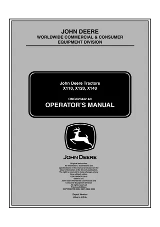
JOHN DEERE WORLDWIDE COMMERCIAL & CONSUMER EQUIPMENT DIVISION John Deere Tractors X110, X120, X140 TM2373 NOVEMBER 2009 TECHNICAL MANUAL Export Version Litho In U.s.a.
INTRODUCTION Introduction Safety Manual Description Specifications and Information Engine (Single Cylinder) Engine (V-Twin) Electrical Power Train (Hydrostatic) Steering Brakes Note: Depending on the particular section or system being covered, not all of the above groups may be used. Attachments Miscellaneous w w
SAFETY Replace Safety Signs Safety Recognize Safety Information Understand Signal Words Special Messages Handle Fluids Safely - Avoid Fires Be Prepared For Emergencies Caution: Avoid Injury! This symbol and text highlight potential hazards or death to the operator or bystanders that may occur if the hazards or procedures are ignored. Important: Avoid Damage! This text is used to tell the operator of actions or conditions that might result in damage to the machine. Note: General information is given throughout the manual that may help the operator in the operation or service of the machine.
https://www.ebooklibonline.com Hello dear friend! Thank you very much for reading. Enter the link into your browser. The full manual is available for immediate download. https://www.ebooklibonline.com
SAFETY Use Care In Handling and Servicing Batteries Wear Protective Clothing Prevent Battery Explosions p p Parking Safely Prevent Acid Burns Avoid acid burns by: Service Machines Safely If you spill acid on yourself: If acid is swallowed:
SAFETY Use Proper Tools Illuminate Work Area Safely DO NOT Work In Ventilated Area Work in Clean Area Before starting a job: Support Machine Properly and Use Proper Lifting Equipment Warning: California Proposition 65 Warning Remove Paint Before Welding or Heating Using High Pressure Washers
SAFETY Avoid Harmful Asbestos Dust Avoid Injury From Rotating Blades and Augers Handle Chemical Products Safely Service Tires Safely Dispose of Waste Properly
SAFETY Live with Safety
SPECIFICATIONS AND INFORMATION TABLE OF CONTENTS Table of Contents Fastener Torques..............................................9 General Information........................................12 Serial Number Locations ...............................15
SPECIFICATIONS AND INFORMATION FASTENER TORQUES Fastener Torques Metric Fastener Torque Values 4.8 12.9 8.8 9.8 10.9 Property Class and Head Markings 12.9 10.9 4.8 8.8 9.8 8.8 4.8 9.8 12.9 10.9 12.9 Property Class and Nut Markings 12 10 10 5 10 10 12 5 10 5 10 12 o Lubricated means coated with a lubricant such as engine oil, or fasteners with phosphate and oil coatings. Dry means plain or zinc plated (Yellow Dichromate - Specification JDS117) without any lubrication
SPECIFICATIONS AND INFORMATION FASTENER TORQUES Metric Fastener Torque Value - Grade 7 Size Steel or Gray Iron Torque Aluminum Torque N m lb-ft N m lb-ft
SPECIFICATIONS AND INFORMATION FASTENER TORQUES Inch Fastener Torque Values 8 5.2 5 5.1 1 or 2b 8.2 SAE Grade and Head Markings No Marks 5 2 8 SAE Grade and Nut Markings No Marks Lubricated means coated with a lubricant such as engine oil, or fasteners with phosphate and oil coatings. Dry means plain or zinc plated (yellow dichromate - Specification JDS117) without any lubrication Grade 2 applies for hex cap screws (Not Hex Bolts) up to 152 mm (6 in.) long. Grade 1 applies for hex cap screws over 152 mm (6 in.) long, and for all other types of bolts and screws of any length. o
SPECIFICATIONS AND INFORMATION GENERAL INFORMATION General Information Gasoline Caution: Avoid Injury! Gasoline is HIGHLY FLAMMABLE, handle it with care.DO NOT refuel machine while: indoors, always fill gas tank outdoors machine is near an open flame or sparks engine is running, STOP engine engine is hot, allow it to cool sufficiently first smoking Help prevent fires: Important: Avoid Damage! DO NOT use METHANOL gasolines because METHANOL is harmful to the environment and to your health. fill gas tank to bottom of filler neck only be sure fill cap is tight after fueling clean up any gas spills IMMEDIATELY Caution: Avoid Injury! California Proposition 65 Warning: Gasoline engine exhaust from this product contains chemicals known to the State of California to cause cancer, birth defects, or other reproductive harm. keep machine clean and in good repair - free of excess grease, oil, debris, and faulty or damaged parts any storage of machines with gas left in tank should be in an area that is well ventilated to prevent possible igniting of fumes by an open flame or spark, this includes any appliance with a pilot light Gasoline Storage To prevent fire or explosion caused by STATIC ELECTRIC DISCHARGE during fueling: Important: Avoid Damage! Keep all dirt, scale, water or other foreign material out of gasoline. ONLY use a clean, approved POLYETHYLENE PLASTIC fuel container and funnel WITHOUT any metal screen or filter John Deere Gasoline Conditioner and Stabilizer (TY15977) ONLY use clean, fresh unleaded gasoline with an octane rating (anti-knock index) of 87 or higher 4 - Cycle Gasoline Engine Oil
SPECIFICATIONS AND INFORMATION GENERAL INFORMATION 5 hours (maximum) TURF - GARD - SAE 10W-30 PLUS - 4 - SAE 10W-30; also recommended TORQ - GARD SUPREME - SAE 30. Important: Avoid Damage! After the break-in period, use the John Deere oil that is recommended for this engine. BREAK-IN OIL SAE 5W-30 SAE 5W-30 Alternative Lubricants SAE 10W-30 SAE 30 Break-In Engine Oil - 4-Cycle Gasoline Important: Avoid Damage! Use of alternative lubricants could cause reduced life of the component. Important: Avoid Damage! ONLY use a quality break-in oil in rebuilt or remanufactured engines for the first 5 hours (maximum) of operation. DO NOT use oils with heavier viscosity weights than SAE 5W-30, these oils will not allow rebuilt or remanufactured engines to break-in properly. Synthetic Lubricants BREAK - IN ENGINE OIL also recommended TORQ - GARD SUPREME - SAE 5W-30.
SPECIFICATIONS AND INFORMATION GENERAL INFORMATION Lubricant Storage Hydrostatic Transmission Oil Important: Avoid Damage! Use ONLY the following oils for service. DO NOT use automatic transmission fluid. Note: The T40 and K46 transmissions are filled with 10W30 engine oil at the factory. Mixing Of Lubricants For the T40 or K46 transmissions used in extreme or high-hour applications, J20C Hygard Hydraulic oil or 5W-50 Synthetic Engine Oil is approved as an optional fill. Use only after a complete drain of the factory oil. Grease Important: Avoid Damage! Use recommended John Deere greases to avoid component failure and premature wear. The recommended John Deere greases are effective within an average air temperature range of -29 to 135 degrees C (-20 to 275 degrees F). If operating outside that temperature range, contact your Servicing dealer for a special-use grease. The following greases are preferred:
SPECIFICATIONS AND INFORMATION SERIAL NUMBER LOCATIONS Serial Number Locations Machine Product Identification Number Transaxle Serial Number Engine Serial Number
ENGINE - SINGLE CYLINDER TABLE OF CONTENTS Table of Contents Specifications .................................................19 Diagnostics .....................................................22 Tests and Adjustments..................................23 Repair...............................................................29
ENGINE - SINGLE CYLINDER SPECIFICATIONS Specifications General Specifications Specifications: Make. . . . . . . . . . . . . . . . . . . . . . . . . . . . . . . . . . . . . . . . . . . . . . . . . . . . . . . . . . . . . . . . . . . . . . . . . . . . . Briggs & Stratton Series. . . . . . . . . . . . . . . . . . . . . . . . . . . . . . . . . . . . . . . . . . . . . . . . . . . . . . . . . . . . . . . . . . . . . . . . . . . . . . . . . . . . . . . Intek Type . . . . . . . . . . . . . . . . . . . . . . . . . . . . . . . . . . . . . . . . . . . . . . . . . . . . . . . . . . . . . . . . . . . . . . . . . . . . . . . . . . . . .Gasoline Stroke/Cycle . . . . . . . . . . . . . . . . . . . . . . . . . . . . . . . . . . . . . . . . . . . . . . . . . . . . . . . . . . . . . . . . . . . . . . . . . . . . . . . . . . . . 4 Models. . . . . . . . . . . . . . . . . . . . . . . . . . . . . . . . . . . . . . . . . . . . . . . . . . . . . . . . . . . . . . . . . . . . . . . . . . . . . . . . . . . . 31P707 Cylinders. . . . . . . . . . . . . . . . . . . . . . . . . . . . . . . . . . . . . . . . . . . . . . . . . . . . . . . . . . . . . . . . . . . . . . . . . . . . . . . . . . . . . . . 1 Valves . . . . . . . . . . . . . . . . . . . . . . . . . . . . . . . . . . . . . . . . . . . . . . . . . . . . . . . . . . . . . . . . . . . . . . . . . . . . Overhead Valves Displacement . . . . . . . . . . . . . . . . . . . . . . . . . . . . . . . . . . . . . . . . . . . . . . . . . . . . . . . . . . . . . . . . . . 502 cm3 (30.63 cu in.) Bore . . . . . . . . . . . . . . . . . . . . . . . . . . . . . . . . . . . . . . . . . . . . . . . . . . . . . . . . . . . . . . . . . . . . . . . . . . . . 90.68 mm (3.57 in.) Stroke . . . . . . . . . . . . . . . . . . . . . . . . . . . . . . . . . . . . . . . . . . . . . . . . . . . . . . . . . . . . . . . . . . . . . . . . . . 77.72 mm (3.06 in.) Cooling System . . . . . . . . . . . . . . . . . . . . . . . . . . . . . . . . . . . . . . . . . . . . . . . . . . . . . . . . . . . . . . . . . . . . . . . . . Air Cooled Lubrication 31P707 engine . . . . . . . . . . . . . . . . . . . . . . . . . . . . . . . . . . . . . . . . . . . . . . . . . . . . . . . . . . . . . . . . Oil Slinger Crankcase Oil Capacity . . . . . . . . . . . . . . . . . . . . . . . . . . . . . . . . . . . . . . . . . . . . . . . . . . . . . . . . . . . . . . . . . 1.4 L (1.5 qt) Air Cleaner . . . . . . . . . . . . . . . . . . . . . . . . . . . . . . . . . . . . . . . . . . . . . . . . . . . . . . . . . . . . Paper with outer foam element Muffler . . . . . . . . . . . . . . . . . . . . . . . . . . . . . . . . . . . . . . . . . . . . . . . . . . . . . . . . . . . . . .Horizontal discharge below frame Fuel Filter . . . . . . . . . . . . . . . . . . . . . . . . . . . . . . . . . . . . . . . . . . . . . . . . . . . . . . . . . . . . . . . . .Replaceable (In-Line Type) Aspiration . . . . . . . . . . . . . . . . . . . . . . . . . . . . . . . . . . . . . . . . . . . . . . . . . . . . . . . . . . . . . . . . . . . . . . . . . . . . . . . . . Normal Alternator . . . . . . . . . . . . . . . . . . . . . . . . . . . . . . . . . . . . . . . . . . . . . . . . . . . . . . . . . . . . . . . . . . . . . . . . . .9 amp regulated Tests and Adjustments Specifications Valve Clearance: Slow Idle (governed) . . . . . . . . . . . . . . . . . . . . . . . . . . . . . . . . . . . . . . . . . . . . . . . . . . . . . . . . . . . . . . . . . . . . . . 1750 rpm Fast Idle. . . . . . . . . . . . . . . . . . . . . . . . . . . . . . . . . . . . . . . . . . . . . . . . . . . . . . . . . . . . . . . . . . . . . . . . . . . . .3350 100 rpm Spark Plug Gap. . . . . . . . . . . . . . . . . . . . . . . . . . . . . . . . . . . . . . . . . . . . . . . . . . . . . . . . . . . . . . . . . . . 0.76 mm (0.030 in.) Spark Plug Torque . . . . . . . . . . . . . . . . . . . . . . . . . . . . . . . . . . . . . . . . . . . . . . . . . . . . . . . . . . . . . . . . 20 N m (180 lb-in.) Valve Clearance - Intake. . . . . . . . . . . . . . . . . . . . . . . . . . . . . . . . . . . . . . . . . . . . . . . . . 0.08 - 0.13 mm (0.003 - 0.005 in.) Valve Clearance - Exhaust. . . . . . . . . . . . . . . . . . . . . . . . . . . . . . . . . . . . . . . . . . . . . . . 0.13 - 0.18 mm (0.005 - 0.007 in.) Valve Guide Depth . . . . . . . . . . . . . . . . . . . . . . . . . . . . . . . . . . . . . . . . . . . . . . . . . . . . . 0.12 - 0.15 mm (0.005 - 0.006 in.) Magneto Air Gap. . . . . . . . . . . . . . . . . . . . . . . . . . . . . . . . . . . . . . . . . . . . . . . . . . . . . . . 0.25 - 0.35 mm (0.010 - 0.014 in.) Repair Specifications Cylinder Bore, Pistons and Rings: Cylinder Bore Maximum Dimension. . . . . . . . . . . . . . . . . . . . . . . . . . . . . . . . . . . . . . . . . . . . . . . . . 90.51 mm (3.563 in.) Cylinder Bore Minimum Dimension . . . . . . . . . . . . . . . . . . . . . . . . . . . . . . . . . . . . . . . . . . . . . . . . . 90.47 mm (3.562 in.) Cylinder Bore Out of Round (maximum) . . . . . . . . . . . . . . . . . . . . . . . . . . . . . . . . . . . . . . . . . . . . . . 0.04 mm (0.002 in.) Piston Pin (Wear Limit . . . . . . . . . . . . . . . . . . . . . . . . . . . . . . . . . . . . . . . . . . . . . . . . . . . . . . . . . . . . 20.29 mm (0.799 in.) Piston Pin Bore (Wear Limit). . . . . . . . . . . . . . . . . . . . . . . . . . . . . . . . . . . . . . . . . . . . . . . . . . . . . . . 20.35 mm (0.801 in.) Ring End Gap (Wear Limit) Case Iron Bore: Compression Ring (Top) . . . . . . . . . . . . . . . . . . . . . . . . . . . . . . . . . . . . . . . . . . . . . . . . . . . . . . . . . . . 0.64 mm (0.025 in.) Compression Ring (Center). . . . . . . . . . . . . . . . . . . . . . . . . . . . . . . . . . . . . . . . . . . . . . . . . . . . . . . . . 0.76 mm (0.030 in.)
ENGINE - SINGLE CYLINDER SPECIFICATIONS Oil Ring . . . . . . . . . . . . . . . . . . . . . . . . . . . . . . . . . . . . . . . . . . . . . . . . . . . . . . . . . . . . . . . . . . . . . . . . . 0.76 mm (0.030 in.) Compression and Oil Ring Groove Wear Limit (New Rings Installed) . . . . . . . . . . . . . . . . . . . . . . 0.15 mm (0.006 in.) Valves: Valve Guide (Wear Limit) . . . . . . . . . . . . . . . . . . . . . . . . . . . . . . . . . . . . . . . . . . . . . . . . . . . . . . . . . . . 6.09 mm (0.240 in.) Valve Seat Width. . . . . . . . . . . . . . . . . . . . . . . . . . . . . . . . . . . . . . . . . . . . . . . . . . . . . . . 0.79 - 1.98 mm (0.031 - 0.078 in.) Valve Margin (Minimum) . . . . . . . . . . . . . . . . . . . . . . . . . . . . . . . . . . . . . . . . . . . . . . . . . . . . . . . . . . . 0.40 mm (0.016 in.) Valve Face Angle . . . . . . . . . . . . . . . . . . . . . . . . . . . . . . . . . . . . . . . . . . . . . . . . . . . . . . . . . . . . . . . . . . . . . . . . . . . . . . .45 Valve Seat Narrowing Angle . . . . . . . . . . . . . . . . . . . . . . . . . . . . . . . . . . . . . . . . . . . . . . . . . . . . . . . . . . . . . . . . . . . . . .30 Connecting Rod and Crankshaft: Connecting Rod Crankpin (Wear Limit) . . . . . . . . . . . . . . . . . . . . . . . . . . . . . . . . . . . . . . . . . . . . . . 38.15 mm (1.502 in.) Connecting Rod Piston Pin Bearing (Wear Limit). . . . . . . . . . . . . . . . . . . . . . . . . . . . . . . . . . . . . . 20.37 mm (0.802 in.) Crankshaft PTO Journal (Wear Limit). . . . . . . . . . . . . . . . . . . . . . . . . . . . . . . . . . . . . . . . . . . . . . . . 41.20 mm (1.622 in.) Crankshaft Magneto Journal (Wear Limit) . . . . . . . . . . . . . . . . . . . . . . . . . . . . . . . . . . . . . . . . . . . . 34.95 mm (1.376 in.) Crankshaft Crankpin Journal (Wear Limit). . . . . . . . . . . . . . . . . . . . . . . . . . . . . . . . . . . . . . . . . . . . 38.02 mm (1.497 in.) Crankshaft Eccentric Journal (Wear Limit) . . . . . . . . . . . . . . . . . . . . . . . . . . . . . . . . . . . . . . . . . . . 55.93 mm (2.202 in.) PTO Bearing (Wear Limit) . . . . . . . . . . . . . . . . . . . . . . . . . . . . . . . . . . . . . . . . . . . . . . . . . . . . . . . . . 41.37 mm (1.629 in.) Magneto Bearing (Wear Limit). . . . . . . . . . . . . . . . . . . . . . . . . . . . . . . . . . . . . . . . . . . . . . . . . . . . . . 35.13 mm (1.383 in.) Crankshaft End Play. . . . . . . . . . . . . . . . . . . . . . . . . . . . . . . . . . . . . . . . . . . . . . . . . . . . 0.05 - 0.58 mm (0.002 - 0.023 in.) Cam Gear PTO Journal (Wear Limit). . . . . . . . . . . . . . . . . . . . . . . . . . . . . . . . . . . . . . . . . . . . . . . . . 12.65 mm (0.498 in.) Cam Gear Magneto Journal (Wear Limit). . . . . . . . . . . . . . . . . . . . . . . . . . . . . . . . . . . . . . . . . . . . . 12.65 mm (0.498 in.) Cam Lobe (Wear Limit) . . . . . . . . . . . . . . . . . . . . . . . . . . . . . . . . . . . . . . . . . . . . . . . . . . . . . . . . . . . 30.07 mm (1.184 in.) Cam Gear Bearing (Wear Limit) . . . . . . . . . . . . . . . . . . . . . . . . . . . . . . . . . . . . . . . . . . . . . . . . . . . . 12.80 mm (0.504 in.) Compression Release Lobe . . . . . . . . . . . . . . . . . . . . . . . . . . . . . . . . . . . . . . . . . . . . . . . . . . . . . . . . 0.25 mm (0.010 in.) Counterweight: Crankshaft Eccentric Journal (Wear Limit) . . . . . . . . . . . . . . . . . . . . . . . . . . . . . . . . . . . . . . . . . . . 55.93 mm (2.202 in.) Counterweight Link Bearing (Wear Limit) . . . . . . . . . . . . . . . . . . . . . . . . . . . . . . . . . . . . . . . . . . . . 56.13 mm (2.210 in.) Torque Specifications (Alphabetical) Specifications: Armature Mounting Screws. . . . . . . . . . . . . . . . . . . . . . . . . . . . . . . . . . . . . . . . . . . . . . . . . . . . . . . . . . 2.8 N m (25 lb-in.) Blower Housing Screws. . . . . . . . . . . . . . . . . . . . . . . . . . . . . . . . . . . . . . . . . . . . . . . . . . . . . . . . . . . . . 10 N m (85 lb-in.) Breather Mounting Bolts . . . . . . . . . . . . . . . . . . . . . . . . . . . . . . . . . . . . . . . . . . . . . . . . . . . . . . . . . . . . . 3 N m (25 lb-in.) Carburetor to Intake Manifold . . . . . . . . . . . . . . . . . . . . . . . . . . . . . . . . . . . . . . . . . . . . . . . . . . . . . . . . . 8 N m (70 lb-in.) Carburetor Bowl Screw . . . . . . . . . . . . . . . . . . . . . . . . . . . . . . . . . . . . . . . . . . . . . . . . . . . . . . . . . . . . . 4.5 N m (40 lb-in.) Connecting Rod Cap Screws . . . . . . . . . . . . . . . . . . . . . . . . . . . . . . . . . . . . . . . . . . . . . . . . . . . . . . . 21 N m (186 lb-in.) Control Bracket Screws. . . . . . . . . . . . . . . . . . . . . . . . . . . . . . . . . . . . . . . . . . . . . . . . . . . . . . . . . . . . . 3.4 N m (30 lb-in.) Cylinder Head Cap Screws . . . . . . . . . . . . . . . . . . . . . . . . . . . . . . . . . . . . . . . . . . . . . . . . . . . . . . . . . 25 N m (220 lb-in.) Drive Belt Idler Pulley. . . . . . . . . . . . . . . . . . . . . . . . . . . . . . . . . . . . . . . . . . . . . . . . . . . . . . . . . . . . . . . 9.6 N m (85 lb-in.) Engine Mounting Bolts . . . . . . . . . . . . . . . . . . . . . . . . . . . . . . . . . . . . . . . . . . . . . . . . . . . . . . . . . . . . . . 32 N m (24 lb-ft) Engine Output Pulley Assembly. . . . . . . . . . . . . . . . . . . . . . . . . . . . . . . . . . . . . . . . . . . . . . . . . . . . . . . 75 N m (55 lb-ft) Exhaust Manifold . . . . . . . . . . . . . . . . . . . . . . . . . . . . . . . . . . . . . . . . . . . . . . . . . . . . . . . . . . . . . . . . 18.5 N m (165 lb-in.) Flywheel Fan Screws . . . . . . . . . . . . . . . . . . . . . . . . . . . . . . . . . . . . . . . . . . . . . . . . . . . . . . . . . . . . . . 16 N m (140 lb-in.) Flywheel Nut . . . . . . . . . . . . . . . . . . . . . . . . . . . . . . . . . . . . . . . . . . . . . . . . . . . . . . . . . . . . . . . . . . . . . 136 N m (100 lb-ft) Flywheel Screen Screws . . . . . . . . . . . . . . . . . . . . . . . . . . . . . . . . . . . . . . . . . . . . . . . . . . . . . . . . . . . . 4.5 N m (40 lb-in.) Fuel Pump Bracket. . . . . . . . . . . . . . . . . . . . . . . . . . . . . . . . . . . . . . . . . . . . . . . . . . . . . . . . . . . . . . . . . 7.3 N m (65 lb-in.)
ENGINE - SINGLE CYLINDER SPECIFICATIONS Fuel Pump to Bracket. . . . . . . . . . . . . . . . . . . . . . . . . . . . . . . . . . . . . . . . . . . . . . . . . . . . . . . . . . . . . . . 4.0 N m (35 lb-in.) Fuel Shutoff Solenoid . . . . . . . . . . . . . . . . . . . . . . . . . . . . . . . . . . . . . . . . . . . . . . . . . . . . . . . . . . . . . . . 5 N m (44 lb-in.) Governor Arm Lock Nut. . . . . . . . . . . . . . . . . . . . . . . . . . . . . . . . . . . . . . . . . . . . . . . . . . . . . . . . . . . . . 4.5 N m (40 lb-in.) Heat Shield Screws . . . . . . . . . . . . . . . . . . . . . . . . . . . . . . . . . . . . . . . . . . . . . . . . . . . . . . . . . . . . . . . . 4.5 N m (40 lb-in.) Ignition Armature . . . . . . . . . . . . . . . . . . . . . . . . . . . . . . . . . . . . . . . . . . . . . . . . . . . . . . . . . . . . . . . . . . 2.8 N m (25 lb-in.) Intake Manifold Elbow . . . . . . . . . . . . . . . . . . . . . . . . . . . . . . . . . . . . . . . . . . . . . . . . . . . . . . . . . . . . . 11 N m (100 lb-in.) Oil Filter Adaptor Screws. . . . . . . . . . . . . . . . . . . . . . . . . . . . . . . . . . . . . . . . . . . . . . . . . . . . . . . . . . . 14 N m (125 lb-in.) Oil Pump Cover Screws. . . . . . . . . . . . . . . . . . . . . . . . . . . . . . . . . . . . . . . . . . . . . . . . . . . . . . . . . . . . . . 9 N m (80 lb-in.) Rocker Arm Adjustment Lock Nut . . . . . . . . . . . . . . . . . . . . . . . . . . . . . . . . . . . . . . . . . . . . . . . . . . . . . 5 N m (45 lb-in.) Rocker Arm Mounting . . . . . . . . . . . . . . . . . . . . . . . . . . . . . . . . . . . . . . . . . . . . . . . . . . . . . . . . . . . . 11.3 N m (100 lb-in.) Spark Plug. . . . . . . . . . . . . . . . . . . . . . . . . . . . . . . . . . . . . . . . . . . . . . . . . . . . . . . . . . . . . . . . . . . . . . . 20 N m (180 lb-in.) Starting Motor Mounting Bolts . . . . . . . . . . . . . . . . . . . . . . . . . . . . . . . . . . . . . . . . . . . . . . . . . . . . . . 16 N m (140 lb-in.) Starting Motor Through Bolts . . . . . . . . . . . . . . . . . . . . . . . . . . . . . . . . . . . . . . . . . . . . . . . . . . . . . . . . . 6 N m (50 lb-in.) Stator to Cylinder Block. . . . . . . . . . . . . . . . . . . . . . . . . . . . . . . . . . . . . . . . . . . . . . . . . . . . . . . . . . . . . 2.3 N m (21 lb-in.) Sump Cover . . . . . . . . . . . . . . . . . . . . . . . . . . . . . . . . . . . . . . . . . . . . . . . . . . . . . . . . . . . . . . . . . . . . . 20 N m (180 lb-in.) Throttle Valve Plate . . . . . . . . . . . . . . . . . . . . . . . . . . . . . . . . . . . . . . . . . . . . . . . . . . . . . . . . . . . . . . . . 4.5 N m (40 lb-in.) Valve Cover Nuts . . . . . . . . . . . . . . . . . . . . . . . . . . . . . . . . . . . . . . . . . . . . . . . . . . . . . . . . . . . . . . . . . . . 6 N m (55 lb-in.) Voltage Regulator/Rectifier . . . . . . . . . . . . . . . . . . . . . . . . . . . . . . . . . . . . . . . . . . . . . . . . . . . . . . . . . . 7.3 N m (65 lb-in.) Special or Essential Tools Special or Required Tools Tool Name Tool No. Tool Use Note: Order tools according to information given in the U.S. SERVICE-GARD Catalog or in the European Microfiche Tool Catalog (MTC).
ENGINE - SINGLE CYLINDER DIAGNOSTICS Other Materials Diagnostics Other Material Starting Problems Part No. Part Name Part Use Caution: Avoid Injury! Be aware! The engine may start to rotate at any time. Keep hands away from all moving parts when testing. Note: To test specific electrical components, see Electrical section and refer to either Diagnostics or Tests and Adjustments for further guidance. Symptom: Engine Will Not Crank Problem Cause - Solution Caution: Avoid Injury! Do not rotate engine with starter if the spark plug is removed. Gasoline spray from the open cylinder may be ignited by ignition spark and cause an explosion or fire. Note: Perform a visual inspection first to determine if battery cables are tight and not corroded. The battery must be sufficient size to turn the engine over at minimum cranking speed of 350 rpm.
ENGINE - SINGLE CYLINDER TESTS AND ADJUSTMENTS Tests and Adjustments Symptom: Engine Cranks But Will Not Start Problem Throttle/Choke Cable Adjustment Cause - Solution Reason: Procedure: A B Fuel Shutoff Solenoid Test Reason: Required Tools: Procedure:
Suggest: If the above button click is invalid. Please download this document first, and then click the above link to download the complete manual. Thank you so much for reading
ENGINE - SINGLE CYLINDER TESTS AND ADJUSTMENTS Procedure: A A Important: Avoid Damage! Do not bend governor link or distort governor arm. Note: If battery voltage drops below 9 volts when cranking engine or while engine is running, the solenoid will not function. B Results: Governor Adjustment - Static C (Engine OFF) Caution: Avoid Injury! Before starting or running engine, static adjustment of the governor must be made. Failure to make static adjustments first, could result in engine overspeeding, and may result in engine or equipment damage, personal injury and/or property damage. Specification: Lock Nut . . . . . . . . . . . . . . . . . . . . . . . 4.5 N m (40 lb-in.) Reason:
https://www.ebooklibonline.com Hello dear friend! Thank you very much for reading. Enter the link into your browser. The full manual is available for immediate download. https://www.ebooklibonline.com

