JCB 1T-1 High Tip Dumper Service Repair Manual Instant Download (SN 2561001 and up)
Please open the website below to get the complete manualnn//
Download Presentation

Please find below an Image/Link to download the presentation.
The content on the website is provided AS IS for your information and personal use only. It may not be sold, licensed, or shared on other websites without obtaining consent from the author. Download presentation by click this link. If you encounter any issues during the download, it is possible that the publisher has removed the file from their server.
E N D
Presentation Transcript
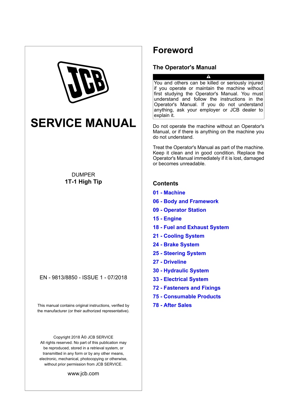
Foreword The Operator's Manual You and others can be killed or seriously injured if you operate or maintain the machine without first studying the Operator's Manual. You must understand and follow the instructions in the Operator's Manual. If you do not understand anything, ask your employer or JCB dealer to explain it. SERVICE MANUAL Do not operate the machine without an Operator's Manual, or if there is anything on the machine you do not understand. Treat the Operator's Manual as part of the machine. Keep it clean and in good condition. Replace the Operator's Manual immediately if it is lost, damaged or becomes unreadable. DUMPER 1T-1 High Tip Contents 01 - Machine 06 - Body and Framework 09 - Operator Station 15 - Engine 18 - Fuel and Exhaust System 21 - Cooling System 24 - Brake System 25 - Steering System 27 - Driveline 30 - Hydraulic System 33 - Electrical System 72 - Fasteners and Fixings 75 - Consumable Products 78 - After Sales EN - 9813/8850 - ISSUE 1 - 07/2018 This manual contains original instructions, verified by the manufacturer (or their authorized representative). Copyright 2018 JCB SERVICE All rights reserved. No part of this publication may be reproduced, stored in a retrieval system, or transmitted in any form or by any other means, electronic, mechanical, photocopying or otherwise, without prior permission from JCB SERVICE. www.jcb.com
15 - Engine 00 - Engine 00 - General Drain and Fill Refer to: PIL 75-03-03. 3. Check the engine oil level. CAUTION Oil will gush from the hole when the drain plug is removed. Keep to one side when you remove the plug. Table 26. Torque Values Item A Description Drain plug (with Copper gasket) Drain plug (with Rubber gasket) Nm 33 37 Drain the oil when the engine is warm as contaminants held in suspension will then be drained with the oil. A 45 53 Drain 1. Make the machine safe. Refer to: PIL 01-03-27. 2. Run the engine for the specified duration. Duration: 5 min 3. Stop the engine. 4. Place a container of suitable size beneath the drain plug. 5. Remove the drain plug. 6. Allow the oil to drain completely. 7. Remove and discard the gasket. 8. Install the drain plug. Figure 45. C B A A Drain plug B Dipstick C Filler cap Fill 1. Tighten the drain plug to the correct torque value. 2. Add recommended oil to the engine through the engine filler. 15 - 20 9813/8850-1 15 - 20
15 - Engine 00 - Engine 00 - General Clean 9. When the pressure washing is complete move the machine away from the wash area, or alternatively, clean away the material washed from the machine. Notice: Clean the engine before you start engine maintenance. Obey the correct procedures. Contamination of the fuel system will cause damage and possible failure of the engine. Notice: The engine and other components could be damaged by high pressure washing systems. Special precautions must be taken if the machine is to be washed using a high pressure system. Make sure that the alternator, starter motor and any other electrical components are shielded and not directly cleaned by the high pressure cleaning system. Do not aim the water jet directly at bearings, oil seals or the engine air induction system. 10. Before working on specific areas of the engine use a compressed air jet to dry off any moisture. When the area is dry use a soft clean brush to remove any sand or grit particles that remain. 11. When removing components be aware of any dirt or debris that may be exposed. Cover any open ports and clean away the deposits before proceeding. Additional cleaning must be carried out prior to working on the high pressure fuel system. Refer to: PIL 18-00-00. Before carrying out any service procedures that require components to be removed, the engine must be properly cleaned. Cleaning must be carried out either in the area of components to be removed or, in the case of major work, or work on the fuel system, the whole engine and surrounding machine must be cleaned. Stop the engine and allow it to cool for at least one hour. DO NOT attempt to clean any part of the engine while it is running. 1. Make sure that the electrical system is isolated. 2. Make sure that all electrical connectors are correctly coupled. If connectors are open fit the correct caps or seal with water proof tape. 3. Cover the alternator with a plastic bag to prevent water ingress. 4. Seal the engine air intake, exhaust and breather system. 5. Make sure that the oil filler caps and dipstick are correctly installed. 6. Use a low pressure water jet and soft bristle brush to soak off caked mud or dirt. 7. Apply an approved cleaning and degreasing agent with a brush. Obey the manufacturers instructions. 8. Use a pressure washer to remove the soft dirt and oil. Important: DO NOT aim the water jet directly at oil seals or electrical connectors and electronic components such as ECU (Electronic Control Unit)'s, alternator or fuel injectors. DO NOT place the jet nozzle closer than the specified distance to any part of the engine or exhaust system. Length/Dimension/Distance: 600 mm 15 - 21 9813/8850-1 15 - 21
https://www.ebooklibonline.com Hello dear friend! Thank you very much for reading. Enter the link into your browser. The full manual is available for immediate download. https://www.ebooklibonline.com
15 - Engine 00 - Engine 00 - General Check (Level) Check (Pressure) 1. Make the machine safe. Refer to: PIL 01-03-27. Compression Pressure This test is used to diagnose suspected poor compression in one or more of the engine cylinders. Use a dummy injector to do the test. 2. Make sure that the machine is in a straight and level condition. 3. Open the engine compartment cover. Refer to: PIL 06-06-06. 1. Make the machine safe. Refer to: PIL 01-03-27. 4. Make sure that the engine is safe to work on. If the engine has been running, let it cool before you start the service work. 2. Run the engine until it is warmed up to its operating temperature. 3. Stop the engine. 5. Remove the dipstick. 4. Set a compression tester with the adaptor to the suitable plug hole. Refer to: PIL 78-94-14. 6. Clean the dipstick. 7. Install the dipstick. 8. Remove the dipstick again. 5. After making sure that the stop lever is set at the stop position (non-injection), run the engine with the starter and measure the compressor pressure. 9. Check that the oil level is between the two marks on the dipstick. 10. If necessary, add recommended oil through one of the filler points. 6. Repeat the above steps for each cylinder. 7. If the measurement is below the allowable limit, apply a small amount of oil to the cylinder wall through the suitable plug hole and measure the compression pressure again. Figure 46. 8. If the compression pressure is still less than the allowable limit, check the top clearance, valve clearance and cylinder head. B MAX A MIN 9. If the compression pressure increases after applying oil, check the cylinder wall and piston rings. 10. Check the compression pressure with the specified valve clearance. 11. Always use a fully charged battery for performing this test. A Oil level B Dipstick 12. Variances in cylinder compression values should be under the specified value. Percentage: 10 % 15 - 22 9813/8850-1 15 - 22
15 - Engine 00 - Engine 00 - General Figure 47. Engine Oil Pressure 1. Make the machine safe. Refer to: PIL 01-03-27. 2. Remove the engine oil pressure switch, and set an oil pressure tester. 3. Start the engine. After warming up, measure the oil pressure at idle and rated speed. 4. If the oil pressure is less than the allowable limit, check the following: Engine oil insufficient. Oil pump defective. Oil strainer clogged. Oil filter cartridge clogged. Oil gallery clogged. Excessive oil clearance. Foreign matter in the relief valve. Figure 48. After checking the engine oil pressure, tighten the engine oil pressure switch to the specified torque value. Table 27. Torque Values Item 1 Description Oil Pressure switch Nm 17.53 15 - 23 9813/8850-1 15 - 23
15 - Engine 00 - Engine 00 - General Calibrate Table 28. Engine Parts Calibration Data Component Illustration Calibration Data Factory Specification 0.145 0.185 mm Description Cold valve clearance Allowable limits - Compression pressure 37.2 41.2 bar ( 539.1 597.1 psi) at 290 RPM (Revolutions Per Minute) Difference among cylinders 10 % or less 22.5 bar ( 326.1 psi) Top clearance 0.55 0.7 mm - Cylinder head surface flat- ness - 0.05 mm Valve recessing -0.05 0.25 mm 0.4 mm 15 - 24 9813/8850-1 15 - 24
15 - Engine 00 - Engine 00 - General Component Illustration Calibration Data Factory Specification 0.035 0.065 mm Description Valve stem to valve guide clearance Allowable limits 0.1 mm Valve stem outside diameter 6.96 6.975 mm - Valve guide inside diameter 7.01 7.025 mm - Valve and valve seat Inlet valve face angle (A) Exhaust valve face angle (A) 45 Inlet valve seat angle (B) Exhaust valve seat angle (B) 45 Inlet valve seat width (C) Exhaust valve seat width (C) 2.12 mm 60 - - - - - - 60 B C A 2.12 mm (1) Valve spring 15 - 25 9813/8850-1 15 - 25
15 - Engine 00 - Engine 00 - General Component Illustration Calibration Data Factory Specification 37 37.5 mm - 117.4 N / 31 mm Description Free length (K) Tilt (L) Setting load / setting length Allowable limits 36.5 mm 1 mm 100 N / 31 mm K L (3) Rocker arm Clearance between rocker arm shaft and rocker arm Rocker arm shaft outside di- ameter Rocker arm inside diameter 0.016 0.045 mm 0.1 mm 11.973 11.984 mm - 12 12.018 mm - Push rod Push rod alignment - 0.25 mm Valve tappet Clearance between tappet and tappet guide Tappet outside diameter Tappet guide inside diame- ter 0.02 0.062 mm 0.07 mm 19.959 19.98 mm 20 20.021 mm - - Timing gear Backlash between crank- shaft gear and idler gear 1 Backlash between idler gear 1 and camshaft gear Backlash between idler gear 1 and injection pump gear Backlash between idler gear 1 and idler gear 2 Backlash between idler gear 2 and governor Backlash between gover- nor gear and Injection pump gear 0.032 0.115 mm 0.15 mm 0.036 0.114 mm 0.15 mm 0.034 0.116 mm 0.15 mm 0.033 0.117 mm 0.15 mm 0.03 0.117 mm 0.15 mm Governor gear 0.03 0.117 mm 0.15 mm Idler gear shaft and bushing Clearance between idler gear 1 shaft and idler gear 1 bushing Idler gear 1 shaft outside di- ameter Idler gear 1 bushing inside diameter Clearance between idler gear 2 shaft and idler gear 2 bushing 0.02 0.054 mm 0.1 mm 25.967 25.98 mm - 26 26.021 mm - 0.02 0.054 mm 0.1 mm 15 - 26 9813/8850-1 15 - 26
15 - Engine 00 - Engine 00 - General Component Illustration Calibration Data Factory Specification 25.967 25.98 mm Description Idler gear 2 shaft outside di- ameter Idler gear 2 bushing inside diameter Allowable limits - 26 26.021 mm - Idler gears Idler gear 1 side clearance Idler gear 2 side clearance 0.2 0.51 mm 0.2 0.51 mm 0.8 mm 0.8 mm Camshaft Camshaft side clearance 0.07 0.22 mm 0.3 mm Camshaft alignment - 0.01 mm Camshaft lobe Camshaft lobe height (In- take) Camshaft lobe height (Ex- haust) 28.8 mm 28.75 mm 29 mm 28.95 mm Camshaft journal and crankcase bore Clearance between camshaft journal and crankcase bore Camshaft journal outside di- ameter Crankcase bore inside diam- eter 0.05 0.091 mm 0.15 mm 35.934 35.95 mm - 36 36.025 mm - Piston pin bore Piston pin bore inside diam- eter 22 22.013 mm 22.05 mm Piston rings 15 - 27 9813/8850-1 15 - 27
15 - Engine 00 - Engine 00 - General Component Illustration Calibration Data Factory Specification 0.085 0.112 mm Description Clearance between second piston ring groove and sec- ond piston ring Clearance between oil ring groove and oil ring Allowable limits 0.2 mm 0.02 0.055 mm 0.15 mm Top piston ring gap Second piston ring gap Oil ring gap 0.25 0.4 mm 0.25 0.4 mm 0.25 0.4 mm 1.25 mm 1.25 mm 1.25 mm Connecting rod Connecting rod alignment - 0.05 mm Piston pin and small end bushing Clearance between piston pin and small end bushing Piston pin outside diameter Small end bushing inside di- ameter 0.014 0.038 mm 0.15 mm 22.002 22.011 mm 22.025 22.04 mm - - Crankshaft Crankshaft alignment - 0.02 mm Crankshaft journal and crankshaft bearing 1 Oil clearance between crankshaft journal and crankshaft bearing 1 Crankshaft journal outside diameter Crankshaft bearing 1 inside diameter 0.034 0.114 mm 0.2 mm 47.934 47.95 mm - 47.984 48.048 mm - Crankshaft journal and crankshaft bearing 2 15 - 28 9813/8850-1 15 - 28
15 - Engine 00 - Engine 00 - General Component Illustration Calibration Data Factory Specification 0.034 0.095 mm Description Oil clearance between crankshaft journal and crankshaft bearing 2 Crankshaft journal outside diameter Crankshaft bearing 2 inside diameter Allowable limits 0.2 mm 47.934 47.95 mm - 47.984 48.029 mm - Crankshaft journal and crankshaft bearing 3 Oil clearance between crankshaft journal and crankshaft bearing 3 Crankshaft journal outside diameter Crankshaft bearing 3 inside diameter 0.034 0.098 mm 0.2 mm 51.921 51.94 mm - 51.974 52.019 mm - Crankpin and crankpin bearing Oil clearance between crankpin and crankpin bear- ing Crankpin outside diameter Crankpin bearing inside di- ameter 0.029 0.091 mm 0.2 mm 39.959 39.975 mm 40.004 40.05 mm - - Crankshaft Crankshaft side clearance 0.15 0.31 mm 0.5 mm Cylinder Cylinder bore inside diame- ter (Standard size) Cylinder bore inside diame- ter (Oversize) 72 72.019 mm 72.15 mm 72.5 72.519 mm 72.65 mm (1) A = Valve face angle, B = Valve seat angle, C = Valve seat width. (2) D = TDC, E = BDC, F = Inlet valve open, G = Exhaust valve open, H = Exhaust valve close, J = Inlet valve close. (3) K = Valve spring length, L = Valve spring tilt. Table 29. Lubrication System Calibration Data Component Illustration Calibration Data Factory Specification More than 0.49 bar ( 7.1 psi) 1.96 4.41 bar ( 28.4 63.9 psi) Description Engine oil pressure at idle speed Engine oil pressure at rated speed Allowable limits - 1.47 bar ( 21.3 psi) 15 - 29 9813/8850-1 15 - 29
15 - Engine 00 - Engine 00 - General Component Illustration Calibration Data Factory Specification 0.06 0.18 mm Description Clearance between inner ro- tor and outer rotor Allowable limits - Clearance between outer ro- tor and pump body 0.1 0.18 mm - Clearance between inner ro- tor and cover 0.025 0.075 mm - Table 30. Cooling System Calibration Data Component Illustration Thermostat Calibration Data Factory Specification Description Allowable limits Valve opening temperature (At beginning) Valve opening temperature (At completion) 69.5 72.5 C ( 157.0 162.4 F) 85 C ( 184.9 F) - - Fan drive belt 7 9 mm - (1) Fan drive belt tension M (1) M = Deflection. Table 31. Fuel System Calibration Data Component Illustration Fuel injection pump Calibration Data Factory Specification Description Allowable limits (1) Injection timing (At 3000RPM) Injection timing (At 3600RPM) 17 19 before TDC (Top Dead Centre) 20 22 before TDC - - N P (2) Fuel tightness 15 - 30 9813/8850-1 15 - 30
15 - Engine 00 - Engine 00 - General Component Illustration Calibration Data Factory Specification - Description Fuel tightness at pump ele- ment Fuel tightness at delivery valve Allowable limits 137.3 bar ( 1,989.8 psi) From 137.3 bar ( 1,989.8 psi) to 127.5 bar ( 1,847.8 psi) in 5 s S R From 137.3 bar ( 1,989.8 psi) to 127.5 bar ( 1,847.8 psi) in 10 s Q Injection nozzle Injection nozzle pressure 137.3 147.1 bar ( 1,989.8 2,131.9 psi) When the pressure is 127.5 bar ( 1,847.8 psi), valve seat must be fuel tight Valve seat tightness (1) N = Timing line, P = Alignment mark. (2) Q = Injection pump pressure tester, R = Injection nozzle, S = Protection cover for jetted fuel Table 32. Engine Electrical System Calibration Data Component Illustration Glow plug resistance Starter Motor Calibration Data Factory Specification Approximately 0.9 Description Allowable limits - Commutator outside diame- ter (For: Planetary gear re- duction type) Commutator outside diame- ter (For: Electromagnetic dri- ve type) Difference outside diameter (For: Planetary gear reduc- tion type) Difference outside diameter (For: Electromagnetic drive type) Mica undercut 30 mm 29 mm 28 mm 27 mm Less than 0.02 mm 0.05 mm Less than 0.05 mm 0.4 mm 0.5 0.8 mm 0.2 mm Brush length 16 mm 10.5 mm Alternator Stator resistance Less than 1 - 15 - 31 9813/8850-1 15 - 31
15 - Engine 00 - Engine 00 - General Component Illustration Calibration Data Factory Specification 2.9 Description Rotor resistance Allowable limits - Slip ring outside diameter 14.4 mm 14 mm Brush length 10 mm 8.4 mm 15 - 32 9813/8850-1 15 - 32
15 - Engine 00 - Engine 00 - General Remove and Install Figure 50. CAUTION This component is heavy. It must only be removed or handled using a suitable lifting method and device. G E Remove 1. Make the machine safe. Refer to: PIL 01-03-27. F 2. Isolate the battery. Refer to: PIL 33-03-03. E Fuel hoses F Fuel filter G Bolt 2 3. Remove the floorplate. Refer to: PIL 09-78-00. 9. Disconnect the electrical connections from the alternator. Refer to: PIL 15-72-00. 4. Remove the engine compartment cover. Refer to: PIL 06-06-06. 10. Disconnect the electrical connections from the starter motor. Refer to: PIL 15-75-00. 5. Remove the radiator. Refer to: PIL 21-03-03. 6. Remove the air filter assembly. 11. Working underneath the machine, remove the exhaust clamp and disconnect the exhaust pipe. 6.1. Loosen the clamps 1. Figure 51. 6.2. Disconnect the air inlet hoses. 6.3. Remove the bolt 1. Figure 49. B J A C H H Exhaust clamp J Exhaust pipe C D B 12. Remove the heat shield from the exhaust pipe. A Air filter assembly B Clamps 1 C Air inlet hoses D Bolt 1 13. Remove the bolt 3 from the exhaust pipe. 14. Remove the exhaust pipe from the machine. 7. Remove the expansion tank. Refer to: PIL 21-06-00. 8. Remove the fuel filter. 8.1. Disconnect the fuel pipe from the filter. 8.2. Remove the bolt 2 and nut 1. 15 - 33 9813/8850-1 15 - 33
15 - Engine 00 - Engine 00 - General Figure 52. 19. Remove the nut and bolts from the engine mounts. 20. Slowly remove the engine from the machine. Figure 55. J K P J Exhaust pipe K Bolt 3 15. Disconnect the fuel pipes. P Engine mounts 16. Disconnect the throttle cable. Figure 53. Install M 1. The installation procedure is the opposite of the removal procedure. L L L Fuel pipes M Throttle cable 17. Remove the wheel drive pump. Refer to: PIL 27-31-00. 18. Support the engine with suitable lifting equipment at the engine lifting eye. Figure 54. N N N Lifting eye 15 - 34 9813/8850-1 15 - 34
Suggest: If the above button click is invalid. Please download this document first, and then click the above link to download the complete manual. Thank you so much for reading
15 - Engine 00 - Engine 00 - General Disassemble and Assemble 17. Remove the valves. Refer to: PIL 15-30-00. Disassemble 18. Remove the thermostat. Refer to: PIL 21-12-00. 1. Make the machine safe. Refer to: PIL 01-03-27. 19. Remove the fan drive pulley. Refer to: PIL 15-18-27. 2. Drain the coolant. Refer to: PIL 21-00-00. 20. Remove the timing gear case. Refer to: PIL 15-51-00. 3. Drain the engine oil. Refer to: PIL 15-00-00. 21. Remove the boost compensator (if installed). Refer to: PIL 18-35-21. 4. Disconnect all the hoses and electrical connectors from the engine. 22. Remove the speed control plates. Refer to: PIL 18-18-21. 4.1. Put a label on the hoses and electrical connectors to help installation. 23. Remove the injection pump. Refer to: PIL 18-18-15. 4.2. Plug all the open ports and hoses to prevent contamination. 24. Remove the camshaft gear, idle gears and governor gear. Refer to: PIL 15-51-00. 5. Remove the air filter assembly. Refer to: PIL 15-24-00. 6. Remove the engine from the machine. Refer to: PIL 15-00-00. 25. Remove the oil sump. Refer to: PIL 15-45-00. 7. Remove the fan belt. Refer to: PIL 15-18-06. 26. Remove the connecting rod. Refer to: PIL 15-33-00. 8. Remove the alternator. Refer to: PIL 15-72-00. 27. Remove the piston. Refer to: PIL 15-36-00. 9. Remove the starter motor. Refer to: PIL 15-75-00. 28. Remove the piston rings. Refer to: PIL 15-36-00. 10. Remove the turbocharger (if installed). Refer to: PIL 18-35-00. 29. Remove the flywheel. Refer to: PIL 15-54-00. 11. Remove the cylinder head cover. Refer to: PIL 15-42-06. 30. Remove the crankshaft and the main bearings. Refer to: PIL 15-12-00. 12. Remove the fuel injections pipes. Refer to: PIL 18-96-03. Assemble 1. The assembly procedure is the opposite of the disassembly procedure. Additionally do the following steps. 13. Remove the injector seal. Refer to: PIL 18-18-07. 14. Remove the rocker arm. Refer to: PIL 15-42-01. 2. Check the condition of each component. 3. Tighten all the fasteners to the correct torque value. 15. Remove the cylinder head. Refer to: PIL 15-06-00. 16. Remove the valve tappets. Refer to: PIL 15-42-21. 15 - 35 9813/8850-1 15 - 35
https://www.ebooklibonline.com Hello dear friend! Thank you very much for reading. Enter the link into your browser. The full manual is available for immediate download. https://www.ebooklibonline.com


