Isuzu A-4BG1, A-6BG1 Diesel Engine Service Repair Manual Instant Download
Please open the website below to get the complete manualnn//
Download Presentation

Please find below an Image/Link to download the presentation.
The content on the website is provided AS IS for your information and personal use only. It may not be sold, licensed, or shared on other websites without obtaining consent from the author. Download presentation by click this link. If you encounter any issues during the download, it is possible that the publisher has removed the file from their server.
E N D
Presentation Transcript
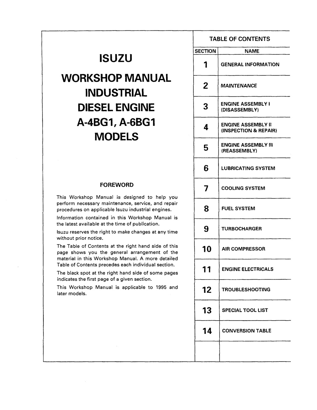
TABLE OF CONTENTS NAME SECTION~ 1 ISUZU GENERAL INFORMATION WORKSHOP MANUAL INDUSTRIAL DIESEL ENGINE A-4BG1, A-6BG 1 MODELS 2 MAINTENANCE ENGINE ASSEMBLY I (DISASSEMBLY) 3 ENGINE ASSEMBLY (INSPECTION & REPAIR) II 4 ENGINE ASSEMBLY (REASSEMBLY) Ill 5 6 LUBRICATING SYSTEM FOREWORD 7 COOLING SYSTEM This Workshop Manual is designed to help you perform necessary maintenance, service, and repair procedures on applicable Isuzu industrial engines. Information contained in this Workshop Manual is the latest available at the time of publication. Isuzu reserves the right to make changes at any time without prior notice. The Table of Contents at the right hand side of this page shows you the general arrangement of the material in this Workshop Manual. A more detailed Table of Contents precedes each individual section. The black spot at the right hand side of some pages indicates the first page of a given section. This Workshop Manual is applicable to 1995 and later models. 8 FUEL SYSTEM 9 TURBOCHARGER 10 AIR COMPRESSOR 11 ENGINE ELECTRICALS 12 TROUBLESHOOTING 13 SPECIAL TOOL LIST 14 CONVERSION TABLE
GENERAL INFORMATION 1-1 SECTION 1 GENERAL INFORMATION TABLE OF CONTENTS PAGE ITEM 1- 2 1- 2 1- 6 1- 8 1-10 1-12 1-23 General repair instructions ............................................................................... Notes on the format of this manual ..................................................................... Main data and specifications ............................................................................. Tightening torque specifications ........................................................................ Angular nut and bolt tightening method ............................................................... Major parts fixing nuts and bolts ........................................................................ Identifications ..............................................................................................
1-2 GENERAL INFORMATION GENERAL REPAIR INSTRUCTIONS 1. Before performing any service operation with the engine mounted, disconnect the grounding cable from the battery. This will reduce the chance of cable damage and burning due to short circuiting. 2. Always use the proper tool or tools for the job at hand. Where specified, use the specially designed tool or tools. 3. Use genuine ISUZU parts referring ISUZU PARTS CATALOG 4. Never reuse cotter pins, gaskets, O-rings, lock washers, and self locking nuts. Discard them as you remove them. Replace them with new ones. 5. Always keep disassembled parts neatly in groups. This will ensure a smooth reassembly operation. It is especially important to keep fastening parts separate. These parts vary in hardness and design, depending on their installation position. 6. All parts should be carefully cleaned before inspection or reassembly. Oil ports and other openings should be cleaned with compressed air to make sure that they are com- pletely free of obstructions. 7. Rotating and sliding part surfaces should be lubricated with oil or grease before reassembly. 8. If necessary, use a sealer on gaskets to prevent leakage. 9. Nut and bolt torque specifications should be carefully followed. 10. Always release the air pressure from any machine-mounted air tank(s) before dismounting the engine or disconnecting pipes and hoses. To not do so is extremely dangerous. 11. Always check and recheck you work. No service operation is complete until you have done this. 12. Information contained in the =Main Data and Specifications" Instruction Book may differ. In this case, the information contained in the Instruction Book should be considered applicable. for the engines surely. of the Workshop Manual and the NOTES ON THE FORMAT OF THIS MANUAL This Workshop Manual is applicable to the 4BG1, 4BGIT, 6BG1, and 6BGIT family of industrial engines. Unless otherwise specified, these engines have common parts and components as well as data and specifications. Illustrations used in this Workshop Manual are based on the 6BG1 and 6BG1T engines. The 4BGIT engine and the 6BGIT engine are turbocharged. 1. Find the applicable section by referring to the Table of Contents at the beginning of the Manual. 2. Common technical data such as general maintenance items, service specifications, torques are included in the "General Information" section. 3. Each section is divided into sub-sections dealing with disassembly, inspection and repair, and reassembly. The section ENGINE ASSEMBLY is an exception. This part is divided into three sections to facilitates quick indexing. 4. When the same servicing operation is applicable to several different units, the manual will direct you to the appropriate page. 5. For the sake of brevity, self-explanatory removal and installation procedures are omitted. More complex procedures are covered in detail. diesel and tightening
https://www.ebooklibonline.com Hello dear friend! Thank you very much for reading. Enter the link into your browser. The full manual is available for immediate download. https://www.ebooklibonline.com
GENERAL INFORMATION 1-3 Each service operation section in this Workshop Manual begins with an exploded view of the applica- ble area. A brief explanation of the notation used follows. 6. Parts marked with an asterisk (*) are included in the repair kit. Parts within a square frame are to be removed and installed as a single unit. --d All parts within an irregularly frame form a single assembly. ]hey are considered a "major component . Individual parts within the irregularly shaped frame are considered "minor components". shaped ---I The number tells you the service opera- tion sequence. Removal of unnumbered parts is unne- cessary unless replacement is required. indicates that a The "* Repair Kit" repair kit is available. D~s~ssembly 1,Wilier ~-plil! boll 2. ThermoIta! housing 3.Waster pump 4. In)ect~on 5. Glow plu0 im l glow plug orme tor 6. Cylinder helCl =over 7. ~Dcker arm shelf1 lind ror~D~ I~m B. Pus~ ; od 9. Cylinder he~Ci Steps - 2 10. Cylir~lr hsaCl gasket 11. ~ rl4~kehott damper ~u==~ seal ~2. Ttming 0liar ~se =:over 13.Taming 0e|r cover 14. T~ning gear Otl piPe 15. ~dltr geJr "B encl lihltt ~, 16.teller peer A" Idler gear ==halt The parts listed Steps" or "Installation Steps" are in the service operation sequence. under "Reassembly pulley with n~z,tle holder The removal or installation marked with a triangle (A) is an import- ant operation. Detailed information is given in the text. of parts Inverlm:~ Erq~ine T 17.
1-4 GENERAL INFORMATION 7. Below is a sample of the text of the Workshop Manual. This is the item shown in the illus- tration. It is marked with a triangle (A) on the Major Components page. ----4 ~ Guidg Inetll|ation~ "I .... ~____.~ ~?. 1. Lu]~he valve guide Outer face with engine OiL 3~rive from the cylinder head upper face. the ~ into posiUot l Special tools are identified by the tool name and/or number. The illustration shows how the spe- cial tool is to be used. L.~ 4. Measure me height of the valve guide upper end from the upger flee of the Cylinder head. t L~--=J~~ Valve Guide Upper End I Height(HI ~1 rnm(in) ~ ~41 m t~ ~ ...... I \ \ Letters and numbers contained in a circle refer to the illustration. N .... I! the valve guide has bee~emoved, the valve guide must be ra l~,aced with new oni~ae a , ~ ~ both the~lve and Symbols indicate the type of service operation or step to be per- formed. A detailed explanation of these symbols follows. Service data and specifications are given in this table 8 The following symbols appear throughout this Workshop Manual They tell you the type of service operation or step to perform. Removal . Adjustment Installation . Cleaning Disassembly Important Operation Requiring Extra Care . Reassembly Specified Torque (Tighten) . Special Tool Use Required or Recommended " (Isuzu Tool or Tools) Alignment (Marks) Commercially Available Tool Use Required or Recommended Directional Indication Inspection .. Lubrication (Oil) D Measurement .. Lubrication (Grease) Sealant Application
GENERAL INFORMATION 1--5 9. Measurement A measurement viceable. "Limit" should be thought of as an absolute value. A measurement which is outside the "limit" indicates that the applicable part or parts must be either repaired or replaced. 10. Components and parts are listed in the singular form throughout the Manual. 11. Directions used in this Manual are as follows: Front The cooling fan side of the engine viewed from the flywheel. Right The injection pump side of the engine. Left The exhaust manifold side of the engine. Rear The flywheel side of the engine. Cylinder numbers are counted from the front of the engine. The front most cylinder is No. 1 and rear most cylinder is No. 4 or No. 6. The engine s direction of rotation is counterclockwise viewed from the flywheel. criteria are defined by the terms "standard" and "limit". falling within the "standard" range indicates that the applicable part or parts are ser- t Right ,hi pompj Left
1-6 GENERAL INFORMATION MAIN DATA AND SPECIFICATIONS Engine Model A-4BG1 A-4BGIT Item Engine type Combustion chamber type Cylinder liner type No. of cylinders - bore x stroke Total piston disptacement --.__..... _ Water cooled, four cycle, vertical in-line overhead valve Direct injection Dry 4 - 105 x 125 (4.13 x 4.92) mm (in) L (cid) 4.329 (464) 17.0 to 1 Compression ratio * Engine dimensions Length x width x height * Engine weight (Dry) Fuel injection order Specified fuel Injection pump Governor Injection nozzle Injection starting pressure MPa (kg/cm2/psi) Fuel filter type Water sedimentor Compression pressure (At warm) Valve clearances (At cold) Intake mm (in) 842 x 645 x 775 (33.1 x 25.4 x 30.5) 325 (716) 878 x 702 x 883 (34.6 x 27.6 x 34.8) 361 (795) mm (in) I i kg (Ib) 1-3-4-2 Diesel fuel (ASTM D975 No. 2D) In-line plunger, Bosch A type Mechanical, RSV type Multi hole 14.7 (150/2,130) Center bolt or cartridge (spin-on) Sediment/water level indicating type 3.04 (31/441) at 200 rpm at sea level 1 18.1 (185/2,630) (If so equipped) MPa (kg/cm2/psi) 0.40 (0.016) 0.40 (0.016) Pressurized circulation Gear type Full flow, cartridge (spin-on) 13.2 (3.5) Water cooled integral type Pressurized forced circulation 8.5 (2.25) Belt driven impeller type Wax pellet type 24-40 Exhaust mm (in) Lubrication method Oil pump Main oil filter type * Lubricating oil volume Oil cooler Cooling method Coolant volume (engine only) Water pump Thermostat type * Generator * Starter * Turbocharger manufacturer * Turbocharger model L (US gal) L (US gal) V-A V-KW 24-4.5 I _ MITSUBISHI TD04H - .. Note: 1. These specifications are based on the standard engine. 2. Specifications for items marked with an asterisk (*) will vary according to the type of equipment on which the engine is installed, If you are unable to locate the data applicable to these specifications, please contact Isuzu Motors LTD through your machine supplier.
GENERAL INFORMATION 1-7 MAIN DATA AND SPECIFICATIONS Engine Model A-6BG1 A-6BGIT Item Engine type Combustion chamber type Cylinder liner type No. of cylinders - bore x stroke Total piston displacement Compression ratio * Engine dimensions Length x width x height * Engine weight (Dry) Fuel injection order Specified fuel Injection pump Governor Injection nozzle Injection starting pressure MPa (kg/cm2/psi) Fuel filter type Water sedimentor Compression pressure (At warm) Valve clearances (At cold) Intake mm (in) Water cooled, four cycle, vertical in-line overhead valve Direct injection Dry mm (in) L (cid) 6 - 105.0 x 125.0 (4.13 x 4.92) 6.494 (396) 17.5 to 1 1122 x 648 x 775 (44.2 x 25.5 x 30.5) 458 (1009) 1-5-3-6-2-4 Diesel fuel (ASTM D975 No. 213) In-line plunger, Bosch AD type Mechanical, RSV type Multi hole 18.1 (185/2,630) Cartridge (spin-on) Sedimenter/water level indicating type 3.04 (31/441) at 200 rpm, at sea level mm (in) 1193 x739 x 949 (47.0 x 29.1 x 37.4) 489 (1078) kg (Ib) (If so equipped) MPa (kg/cm2/psi) 0.40 (0.016) 0.40 (0.016~ Pressurized circulation Gear type Centerbolt, fullflow or cartridge (spin-on) Equipped by OEM Exhaust mm (in~ Lubrication method Oil pump Main oil filter type Partial oil filter I* Lubricating oil volume L (US gel) 21.5 (5.68) Water cooled integral type Pressurized forced circulation 12 (3.2) Belt driven impeller type Wax pellet type Oil cooler Cooling method Coolant volume (engine only) Water pump Thermostat type L (US gal) * Generator * Starter * Turbocharger manufacturer * Turbocharger model V-A V-KW 24-40 24-4.5 IHI -- RHE6 I Note: 1. These specifications are based on the standard engine. 2. Specifications for items marked with an asterisk (*) will vary according to the type of equipment on which the engine is installed. If you are unable to locate the data applicable to these specifications, please contact Isuzu Motors LTD through your machine supplier.
1-8 GENERAL INFORMATION TIGHTENING TORQUE SPECIFICATIONS The tightening torque values given in the table below are applicable to the bolts unless otherwise specified. STANDARD BOLT Bolt ~ so. \ o!..~,to, ~ \ pitch (mm} N.m (kgf.m) ation M6 xl.0 7.8{ 0.4~ 0.8} 4.9~ 3.9~ 9.8 { 0.5~ 1.0} M8 xl.25 7.8~ 17.7 { 0.8~ 1.8} 11.8~ 22.6{ 1.2~ 2.3} 16.7~ 30.4{ 1.7~ 3.1} M10 x 1.25 20.6~ 34.3 { 2.1~ 3.5} 27.5~ 46.1 { 2.8~ 4.7} 37.3~ 62.8 { 3.8~ 6.4} 19.6~ 33.4 { 2.0~ 3.4} 27.5~ 45.1 { 2.8~ 4.6} * MIO x 1.5 36.3~ 59.8 { 3.7~ 6.1} M12 x 1.25 49.1~ 73.6 { 5.0~ 7.5} 60.8~ 91.2 { 6.2~ 9.3} 75.5~114.0 { 7.7~11.6) 45.1~ 68.7 { 4.6~ 7.0} M12 x 1.75 56.9~ 84.4 { 5.8~ 8.6} 71.6~107.0 { 7.3~10.9} 76.5~115.0 { 7.8~11.7} 93.2~139.0 { 9.5~14.2} 114.0~171.0 {11.6~17.4} M14 x 1.5 M14 x 2.0 71.6~107.0 { 7.3~10.9} 88.3~131.0 { 9.0~13.4} 107.0~160.0 {10.9~ 16.3} 104.0~157.0 {10.6~ 16.0) 135.0~204.0 {13.8~20.8} M16 x 1.5 160.0~240.0 {16.3~24.5} M16 x 2.0 100.0~149.0 {10.2~15.2} 129.0~194.0 {13.2~19.8} 153.0~230.0 {15.6~23.4} M18 x 1.5 195.0~293.0 {19.9 ~29.9} 151.0~226.0 {15.4~23.0} 230.0~345.0 {23.4~35.2} 151.0~226.0 {15.4~23.0} 196.0~294.0 {20.0~30.0} 231.0~346.0 {23.6~35.3} M18 x 2.5 M20 x 1.5 270.0~405.0 {27.5~41.3} 206.0~310.0 {21.0~31.6) 317.0~476.0 {32.3~48.5} M20 x 2.5 190.0~286.0 {19.4~29.2} 249.0~375.0 {25.4~38.2} 293.0~440.0 {29.9~44.9} M22 x 1.5 251.0~414.0 {25.6~42.2} 363.0~544.0 {37.0~55.5} 425.0~637.0 {43.3~64.9} M22 x 2.5 218.0~328.0 {22.2~33.4} 338.0~507.0 {34.5~51.7} 394.0~592.0 {40.2~60.4} M24 x 2.0 359.0~540.0 {36.6~55.0) 431.0~711.0 {43.9~72.5} 554.0~831.0 {56.5~84.7} M24 x 3.0 406.0~608.0 (41.4~62.0} 338.0~507.0 {34.5~51.7} 521.0~782.0 {53.1~79.7} An asterisk (*) indicates that the bolts are used for female threaded parts that are made of soft materials such as casting.
GENERAL INFORMATION 1-9 TIGHTENING TORQUE SPECIFICATIONS The tightening torque values given in the table below are applicable to the bolts unless otherwise specified. ~ Diameter x pitch (ram) FLANGED HEAD BOLT Bolt tion N-m (kgf.m) 4.6~ 6.6~ 12.2 { 0.6~ 1.2} M6 xl.0 8.5{ 0.5~ 0.9} M8 xl.25 10.5~ 196 ( 1.1~ 2.0) 15.3~ 28.4{ 1.6~ 2.9} 18.1~ 33.6{ 2.1~ 3.4} 35.4~ 58.9 { 3.6~ 6.1} . M10 x 1.25 23.1~ 38.5 { 2.4~ 3.9} 42.3~ 70.5{ 4.3~ 7.2} 34.5~ 57.5 { 3.5~ 5.8} 40.1~ 66.9{ 4.1~ 6.8} * M10 x 1.5 22.3~ 37.2 { 2.3~ 3.8} M12 x 1,25 54.9~ 82.3 { 5,6~ 8.4} 77.7~117.0 { 7.9~11.9} 85.0~128.0 ( 8.7~13.0} * M12 x 1.75 51,0~ 76.5 { 5.2~ 7.8} 71.4~107.0 { 7.3~10.9} 79.5~119.0 { 8.1~12.2) 83.0~125.0 { 8.5~12.7} 115.0~172.0 {11.7~17.6} 123.0~185.0 {12.6~18.9} M14 x 1.5 77,2~116.0 { 7.9~11.8} 108.0~162.0 {11.1~16.6} 116.0~173.0 {11.8~17.7) M14 x 2.0 116.0~173.0 {11.8~17.7} 171.0~257.0 {17.4~26.2) 177.0~265.0 {18.0~27.1} M16 x 1.5 109.0~164.0 {11.2~16.7} 163.0~244.0 {16.6~24.9} 169.0~253.0 {17.2~25.8} * M16 x 2.0 A bolt with an asterisk (*) is used for female screws of soft material such as cast iron.
1-10 GENERAL INFORMATION ~ ANGULAR NUT AND BOLT TIGHTENING METHOD 1. Carefully wash the nuts and bolts to remove all oil and grease. 2. Apply a coat of molybdenum threads and setting faces of the nuts and bolts. disulfide grease to the 3. Tighten the nuts and bolts to the specified torque (snug torque) with a torque wrench. n 4. Draw a line [A-B] across the center of each bolt. Center line
GENERAL INFORMATION 1-11 Draw another line (C-D) on the face of each of the parts to be clamped. This line should be an exten- sion of the line [A-B]. 5o Line / Draw another line iF-G] on the face of each of the parts to be clamped. This line will be in the direc- tion of the specified angle (Q) across the center [E] of the nut or bolt. , \\ k J Specified angle (Qt G Coinciding line Use a socket wrench to tighten each nut or bolt to the point where the line [A-B] is aligned with the line iF-G]. 7. O C [~~Tighten Example: Specified Angle and Tightening Rotation 30 60 90 = 180 = 360" 1/12 of a turn 1/6 of a turn 1/4 of a turn 1/2 of a turn One full turn A B C D E
1-12 GENERAL INFORMATION [~-7 MAJOR PART FIXING NUTS AND BOLTS Cylinder Head and Cover N.m (kgf.m/ft.lb $ ,o ~-,"~ ,2, For laminated steel sheet gasket Apply MoS2 grease Glow plug 42-62 1(4.3-6.3/31-46) Mos2 ...... Molybdenum disulfide paste.
GENERAL INFORMATION 1-13 Cylinder Body N-m (kgf.m/ft.lb) 42-62 (4.3-6.3/31-46] 21-30 2.1-3.1115-22] 21-3o ! [2.1-3.1/15-22) I ~ ~ 21-30 (2.1-3.1/15-22) Apply engine oil 16-25 1 (1.6-2.6/12-19) t
1-14 GENERAL INFORMATION Oil Pan and Dipstick N.m (kgf.m/ft.lb) 25-30 [2.6-3.1/19-22) % 21-30 (2.1-3.1/15-22] I 69-88 (7-9151-65)
GENERAL INFORMATION 1-15 Camshaft and Rocker Arm N.m (kgf.m/ft.lb) 25-35 {2.6--3.6/19-26) 20-29 (2.0-3.0/15-22) 6B 4B 25--35 (2.6-3.6/19-26) 20-29 (2.0-3.0/15-22) 6B 4B 2) ,I o,, with ,14.5-11742~117:5-127; Lubricate 1~ engine ~ 44-64 (4.5-6.5/33-47) 42.-62 (4.3-.6.3/31-46} 6B 4B
1-16 GENERAL INFORMATION Crankshaft, Piston, and Flywheel N.m (kgf.m/ft.lb) 39 (4129) Apply MoS2 grease .~60o_90 o /O 6B 4B 539--637 (55-651378-470) (39-491282-354) Apply MoSz grease 380-481 Apply engine oil
Suggest: For more complete manuals. Please go to the home page. https://www.ebooklibonline.com If the above button click is invalid. Please download this document first, and then click the above link to download the complete manual. Thank you so much for reading
GENERAL INFORMATION 1-17 Thermostat and Thermostat Housing N.m (kgf.m/ft.lb) 21-30 I (2.1-3.1/15-22) / 42-62 [4.3-6.3131-46) ~ "~
1-18 GENERAL INFORMATION Intake and Exhaust Manifold N.m (kgf.m/ft.lb) 21-30 12.1-3.1/15-2211 42-62 (4.3-6.3/31-46) 22-31 (2.2-3.2/16-23) 6B 4B :%- -/ 1,-24 (1.,-2.4/10-17) "~L~/~) 1(4.3-6.3/31-46) 6B 4B 25-31 (2.6-3.2/19-23) 16-25 (1.6-2.6/12-19)
https://www.ebooklibonline.com Hello dear friend! Thank you very much for reading. Enter the link into your browser. The full manual is available for immediate download. https://www.ebooklibonline.com

